Transmitting system and transmitting apparatus

a transmission system and transmission line technology, applied in the field of transmission system and transmission line, can solve the problems of recording and reproducing apparatus, inability to realize effective use of the transmission line, etc., and achieve the effect of reducing the amount of data to be transmitted on the transmission lin

Inactive Publication Date: 2003-06-10
PANASONIC CORP
View PDF7 Cites 13 Cited by
  • Summary
  • Abstract
  • Description
  • Claims
  • Application Information

AI Technical Summary

Benefits of technology

It is an object of the present invention to provide a transmitting system which is capable of transmitting data in such a man...

Problems solved by technology

This makes it impossible to realize effective use of the band of the transm...

Method used


Image

  • Transmitting system and transmitting apparatus
  • Transmitting system and transmitting apparatus
  • Transmitting system and transmitting apparatus

Examples


embodiment 1

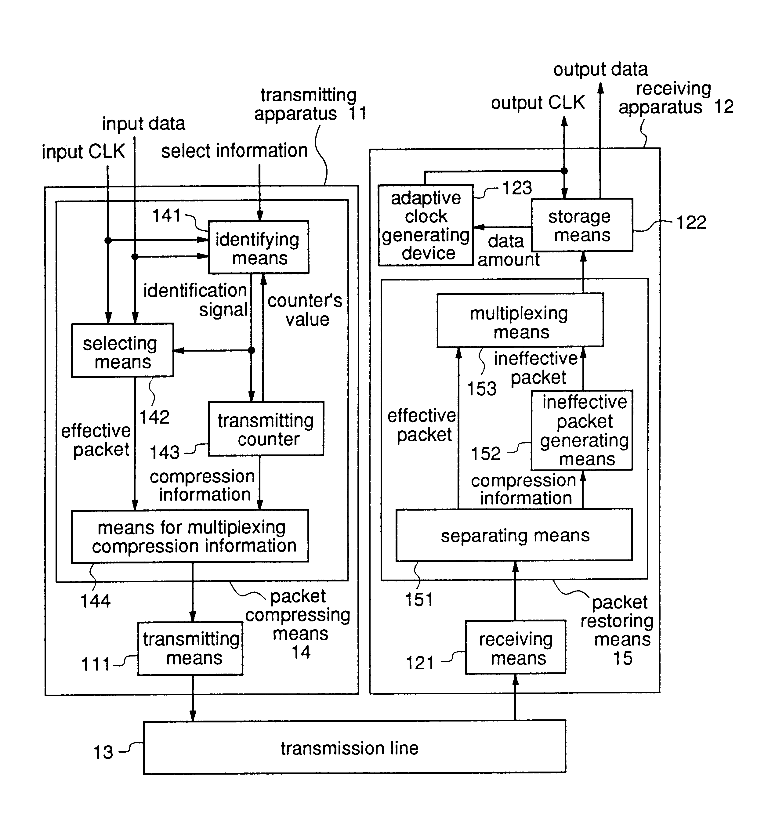
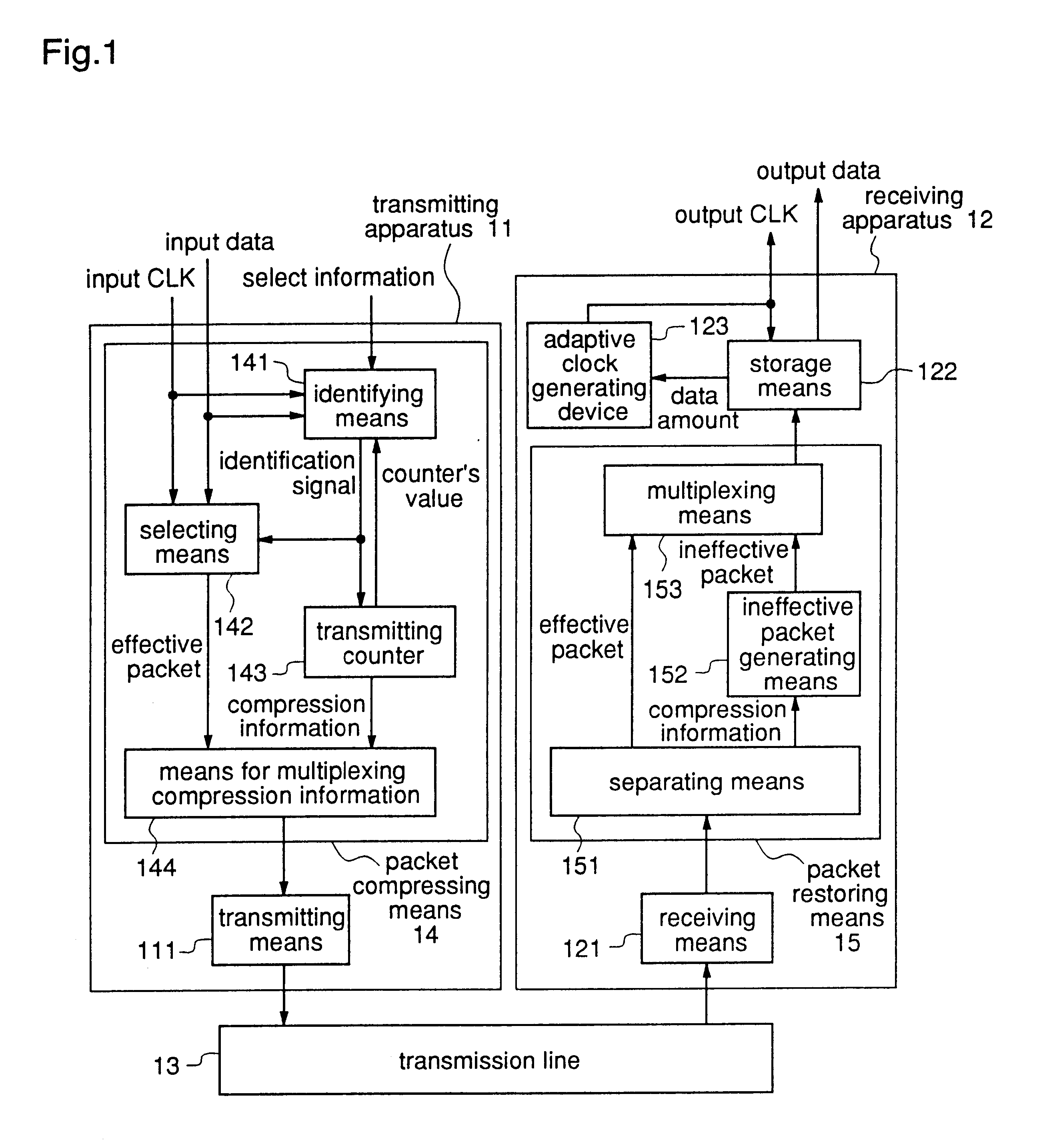
FIG. 1 shows a construction of a transmitting system of the first embodiment. In FIG. 1, reference numerals 11, 12, and 13 designate a transmitting apparatus, a receiving apparatus, and a transmission line, respectively. The transmitting apparatus 11 comprises packet compressing means 14 and transmitting means 111. The packet compressing means 14 comprises identifying means 141, selecting means 142, a transmitting counter 143, and means for multiplexing compression information (multiplexing means) 144. The receiving apparatus 12 comprises packet restoring means 15, receiving means 121, storage means 122, and an adaptive clock generating device 123. The packet restoring means 15 comprises separating means 151, ineffective (null) packet generating means 152, and multiplexing means 153. Hereinafter, a description will be given of operation of the first embodiment with reference to FIG. 1.

First, operation of the transmitting apparatus 11 will be described.

The transmitting apparatus 11 r...

embodiment 2

A description will now be given of a receiving apparatus in a transmitting system according to a second embodiment of the present invention with reference to FIG. 6.

Turning now to FIG. 6, reference numerals 611, 612, 613, 614, 615, 64, 641, 642, 643, 644, and 645 designate receiving means, storage means, separating means, means for computing data amount (computing means), adaptive clock generating device, packet restoring means, packet separating means, a receiving counter, control means, means for generating ineffective packets (generating means), and multiplexing means, respectively.

The receiving apparatus of this embodiment has replaced the receiving apparatus 12 of the first embodiment, and is adapted to receive the compressed data transmitted from the transmitting means 11.

The receiving means 611 receives the compressed data on the transmission line, which is then stored in the storage means 612. The storage means 612, in response to a read request from the control means 643, o...

embodiment 3

Hereinafter, a description will be given of a recording and reproducing apparatus according to a third embodiment of the present invention with reference to FIG. 7.

In FIG. 7, reference numerals 71, 72, and 73 designate a recording apparatus, a reproducing apparatus, and a recording medium, respectively. The recording apparatus 71 comprises recording means 711, and packet compressing means 74. The reproducing apparatus 72 comprises reproducing means 721, clock generating means 722, and packet restoring means 75. The packet restoring means 75 comprises packet separating means 751, a receiving counter 752, control means 753, ineffective packet generating means 754, and multiplexing means 755.

Operation of the recording apparatus 71 will be described.

The operation of the packet compressing means 74 of the recording apparatus 71 is identical to that of the packet compressing means 14 of the transmitting apparatus of the first embodiment, and therefore, will not be discussed herein. The co...


PUM


Abstract

A transmitting system which comprises a transmission line, a transmitting apparatus connected to the transmission line, and a receiving apparatus connected to the transmission line, and transmits data between the transmitting apparatus and the receiving apparatus, wherein the transmitting apparatus comprises packet compressing means which receives input data comprising plural packets having identifiers as an input, identifies packets to be discarded and effective packets according to the identifiers, and outputs compression information indicating the number of continuously discarded packets and the effective packets to the transmission line, and the receiving apparatus comprises packet restoring means which receives the compression information and the effective packets which have been output from the transmitting apparatus, generates ineffective, packets which are as many as the discarded packets, and outputs the ineffective packets and the effective packets.

Description

The present, invention relates to a transmitting system, apparatus, a recording and reproducing apparatus, and a recording apparatus, for transmitting / recording a stream comprising plural packets according to MPEG (Moving Picture Experts Group)2.BACKGROUND OF THF INVENTIONIt has been well known that a TS (transport stream) according to MPEG2 i , a stream comprising compressed digital video, compressed digital audio, and the like. The TS is used in digital broadcasting, and contains multiplexed plural programs. Hereinafter, "TS" always refers to the TS according to MPEG2 (MPEG2 TS). MPEG2 is defined in ITU-T H.222.0 (ISO / IEC 13818-1) "Generic Coding of Moving Pictures And Associated Audio Information".FIGS. 3(a) and 3(b) show the TS. Shown in FIG. 3(a) are TS packets. The TS comprises a set of TS packets which are fixed in length (188 byte). The TS packets each includes plural fields, i.e., 8-bit Sync Byte, a 13-bit PID (Packet identifier), a 4-bit CC (Continuity Counter), an AF (Ada...

Claims


Application Information

Patent Timeline
IPC IPC(8): H04N7/24H04N7/52H04L29/06H04N7/62H04J3/00H04L7/04H04N5/765H04L47/20H04L47/2416H04L49/9023H04N5/781H04N5/92H04N7/08H04N7/081H04N19/00H04N19/102H04N19/152H04N19/196H04N19/426H04N19/44H04N19/65H04N19/70H04N19/89H04N21/236H04N21/2389H04N21/43H04N21/432H04N21/433H04N21/434H04N21/4385H04N21/6332
CPCH04N21/23614H04N21/2389H04N21/4305H04N21/4325H04L69/04H04N21/4348H04N21/4385H04N21/6332H04N21/4334
Inventor IBARAKI, SUSUMUHATTORI, TOSHIKAZUMURAKAMI, HIROKI
Owner PANASONIC CORP
Why Eureka
Try Eureka