Cable retention system

a cable and cable technology, applied in the direction of cables, insulated conductors, coupling device connections, etc., can solve the problems of signal degradation, prior systems are unable to secure the cable against unwanted motion, and it is not always desirable or practical to connect the cabl

Inactive Publication Date: 2003-06-24
HEWLETT PACKARD DEV CO LP
View PDF12 Cites 33 Cited by
  • Summary
  • Abstract
  • Description
  • Claims
  • Application Information

AI Technical Summary

Problems solved by technology

Nevertheless, it is not always desirable or practical to connect the cable to ground at its terminus.
Further, in the case of bulkhead connectors, a continuing problem exists with securing the cables against unwanted motion that can, for example, cause signal degradation by torsional or translational motion of the cable.
Prior systems are unable to secure the cable against unwanted motion while providing a ground for the EMI shielding.
Additionally, stricter EMI limits are necessarily imposed by the practicalities of operating computer and telecommunications systems at increasingly faster rates of data transmission.

Method used


Image

  • Cable retention system
  • Cable retention system
  • Cable retention system

Examples


Embodiment Construction

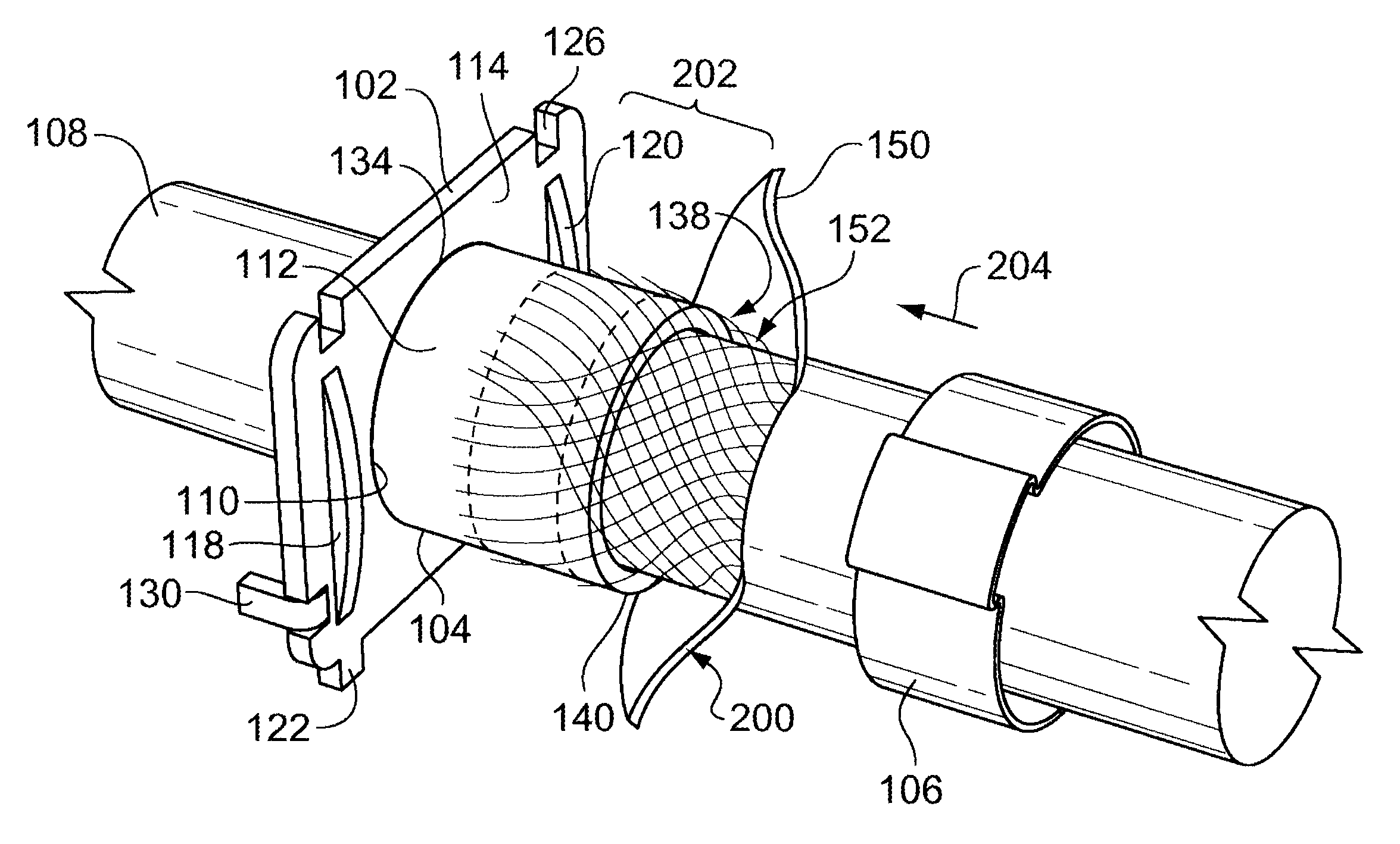
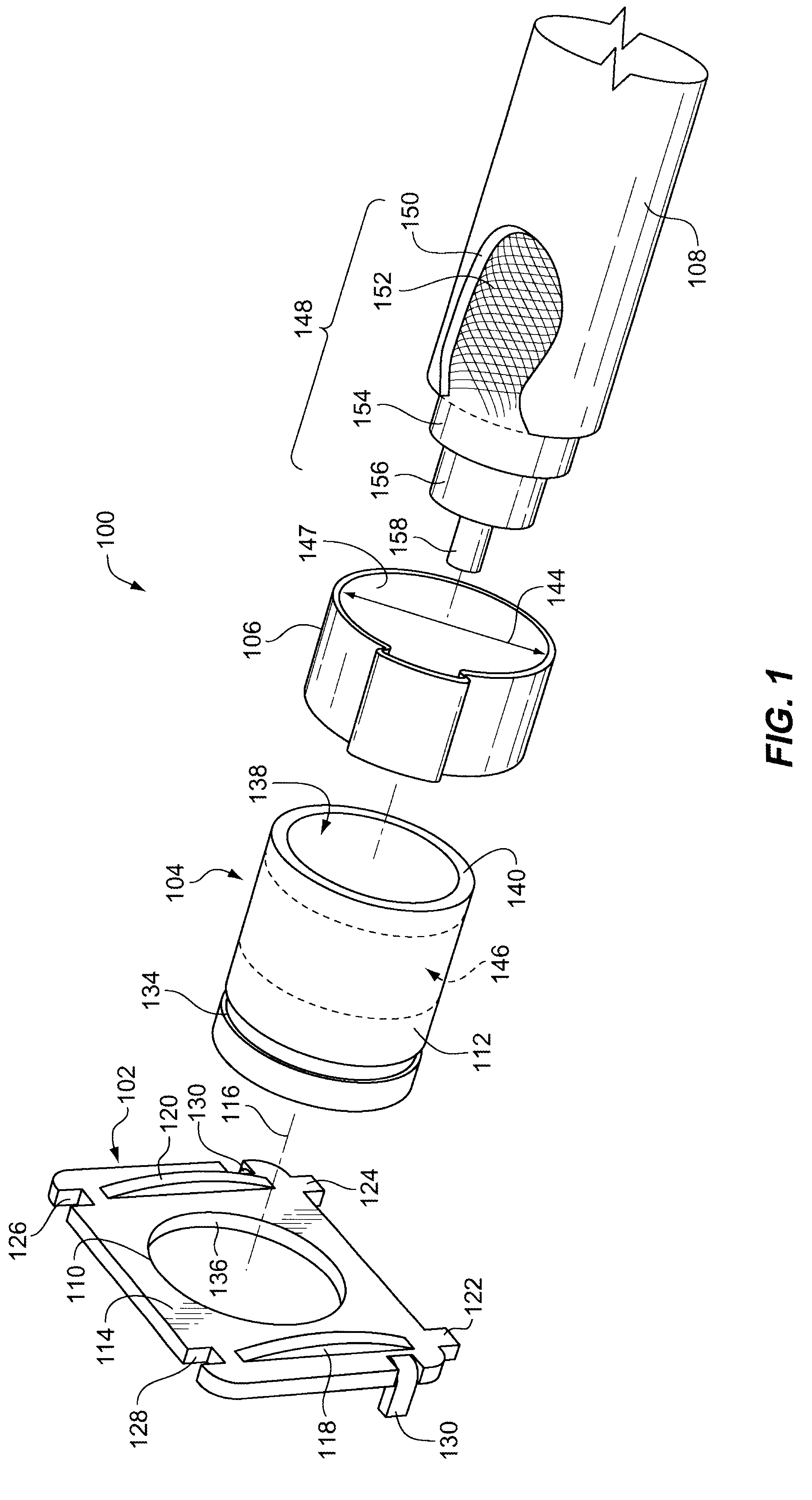
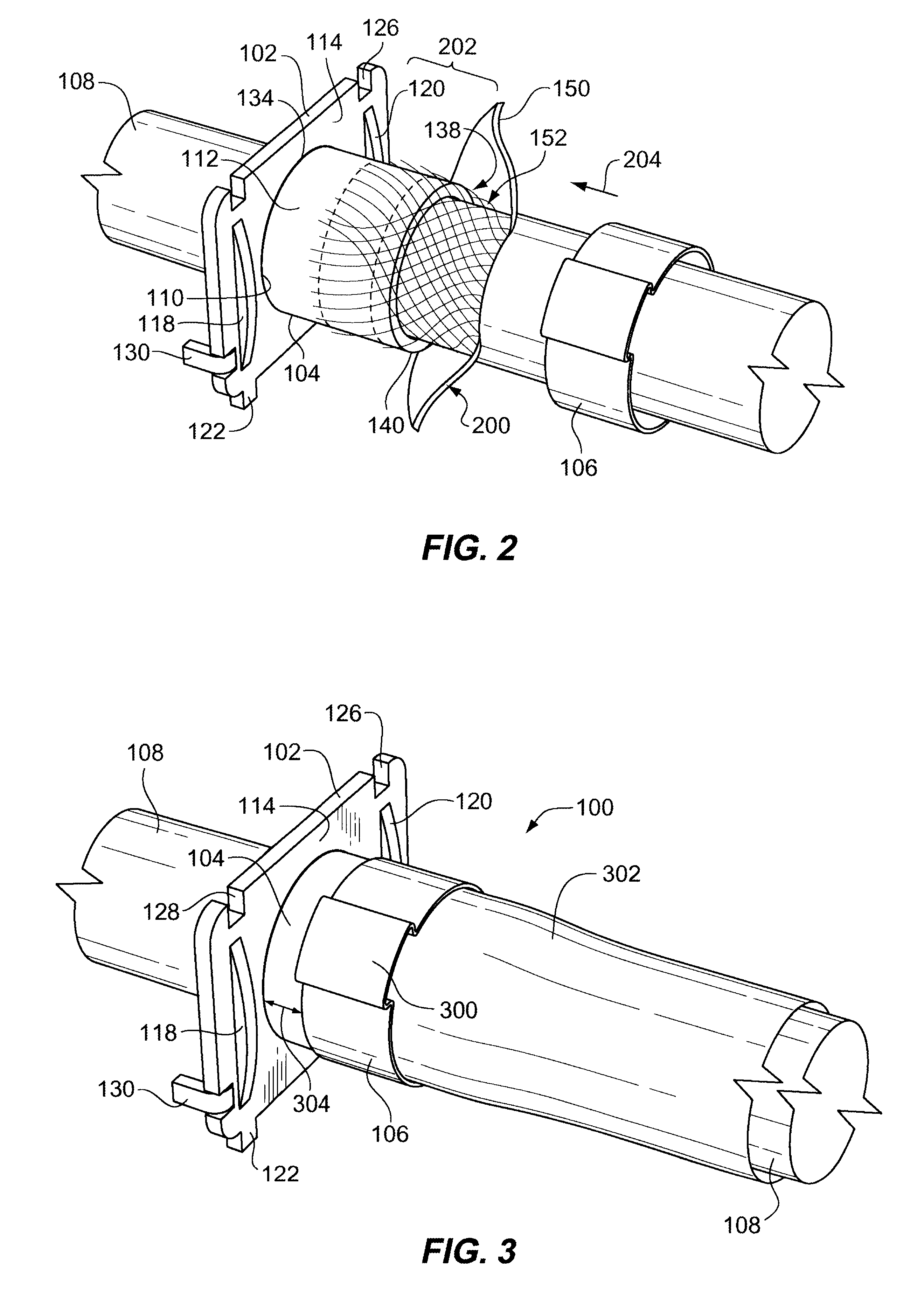
FIG. 1 depicts a right front assembly view of a cable retention device 100 including an end plate 102 that is press-fit with a cylindrical conduit 104. A clamp 106 is used to retain a shielded cable 108 on the conduit 104 in a manner that does not compress or kink the shielded cable 108. The end plate 102 and conduit 104 are preferably made of a conductive material, such as brass, steel, or conductively enhanced plastic.

The end plate 102 defines an aperture 110 of sufficient dimensions to circumscribe an exterior surface 112 of the conduit 104. Thus, once assembled with the cylinder 104, the end plate 102 essentially forms a shoulder surrounding the cylinder 104 and includes a front face 114 extending transversely with respect to an axis of symmetry 116 in the conduit 104. A pair of arches 118 and 120 rise from front face 114 and function as fulcrums in flexion of a guide rail mounting bracket that is to be discussed in the context of additional figures.

In preferred but optional emb...


PUM


Abstract

A cable retention device includes a conduit that is joined to an end plate forming a continuous passage through the conduit. Cable shielding is clamped to the conduit to establish a pathway to ground. The end plate presents a shoulder face that is inserted into a guide rail clamp. The shoulder face includes a pair of arches that function as fulcrums to flex the guide rail bracket, which secures the cable retention device to a chassis under compressive force.

Description

1. Field of the InventionThe invention pertains to the field of fittings and adaptors that can be used to secure insulated electrical cables for the transmission of signals. More specifically, the fittings and adaptors are used to retain cables that are shielded from the effects of electromagnetic disturbances.2. Discussion of the Related ArtCables for use in transmitting electronic signals are often provided with shielding in the form of foil, wire mesh or screen material that surrounds one or more central insulated leads. One common example of this type of cable is the coaxial cable that is used to carry television or data transmissions. The shielding itself is usually covered with an external layer of insulation. The shielding protects the wanted signal that is being transmitted on the central lead from ambient electromagnetic disturbances. The shielding also limits the amount of electromagnetic disturbance that is transmitted outwardly from the central lead. For these reasons, s...

Claims


Application Information

Patent Timeline
Patent Type & Authority Patents(United States)
IPC IPC(8): H02G3/02H02G3/06H02G3/22F16L3/08H02G3/30
CPCH02G3/0666H02G3/22Y10T16/05
Inventor RUBENSTEIN, BRANDONCLEMENTS, BRADLEY E
Owner HEWLETT PACKARD DEV CO LP
Why Eureka
Try Eureka