Fiber optic assembly and method of making same

Inactive Publication Date: 2003-06-24
CCS TECH INC
View PDF13 Cites 51 Cited by
  • Summary
  • Abstract
  • Description
  • Claims
  • Application Information

AI Technical Summary

Benefits of technology

The present invention seeks to overcome the problems noted above by providing an optical fiber assembly in which two or more optical fibers are tacked to each other to prevent relative sliding therebetween, while allowing the fibers to be easily detached when desired. In accordance with a first aspect of the invention, the optical fiber assembly comprises a plurality of optical fibers arranged parallel to one another such that each optical fiber is closely adjacent to at least one other optical fiber, and a web of material disposed between each pair of adjacent optical fibers and bound

Problems solved by technology

This movement between the fibers makes it difficult to place each fiber i

Method used


Image

  • Fiber optic assembly and method of making same
  • Fiber optic assembly and method of making same
  • Fiber optic assembly and method of making same

Examples


Embodiment Construction

The present invention will be described more fully hereinafter with reference to the accompanying drawings, in which preferred embodiments of the invention are shown. This invention may, however, be embodied in many different forms and should not be construed as limited to the embodiments set forth herein; rather, these embodiments are provided so that this disclosure will be thorough and complete, and will fully convey the scope of the invention to those skilled in the art. Like numbers refer to like elements throughout.

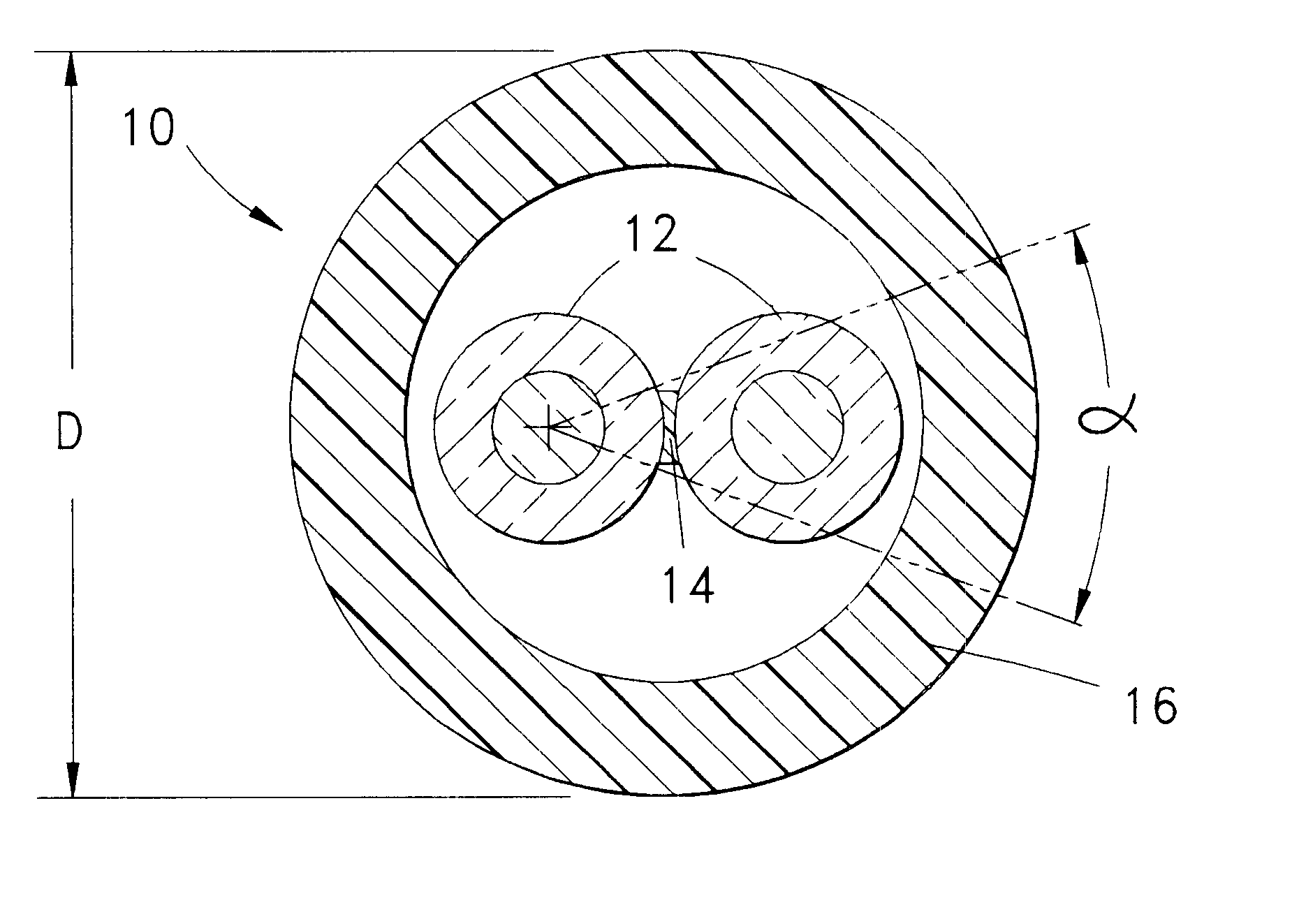
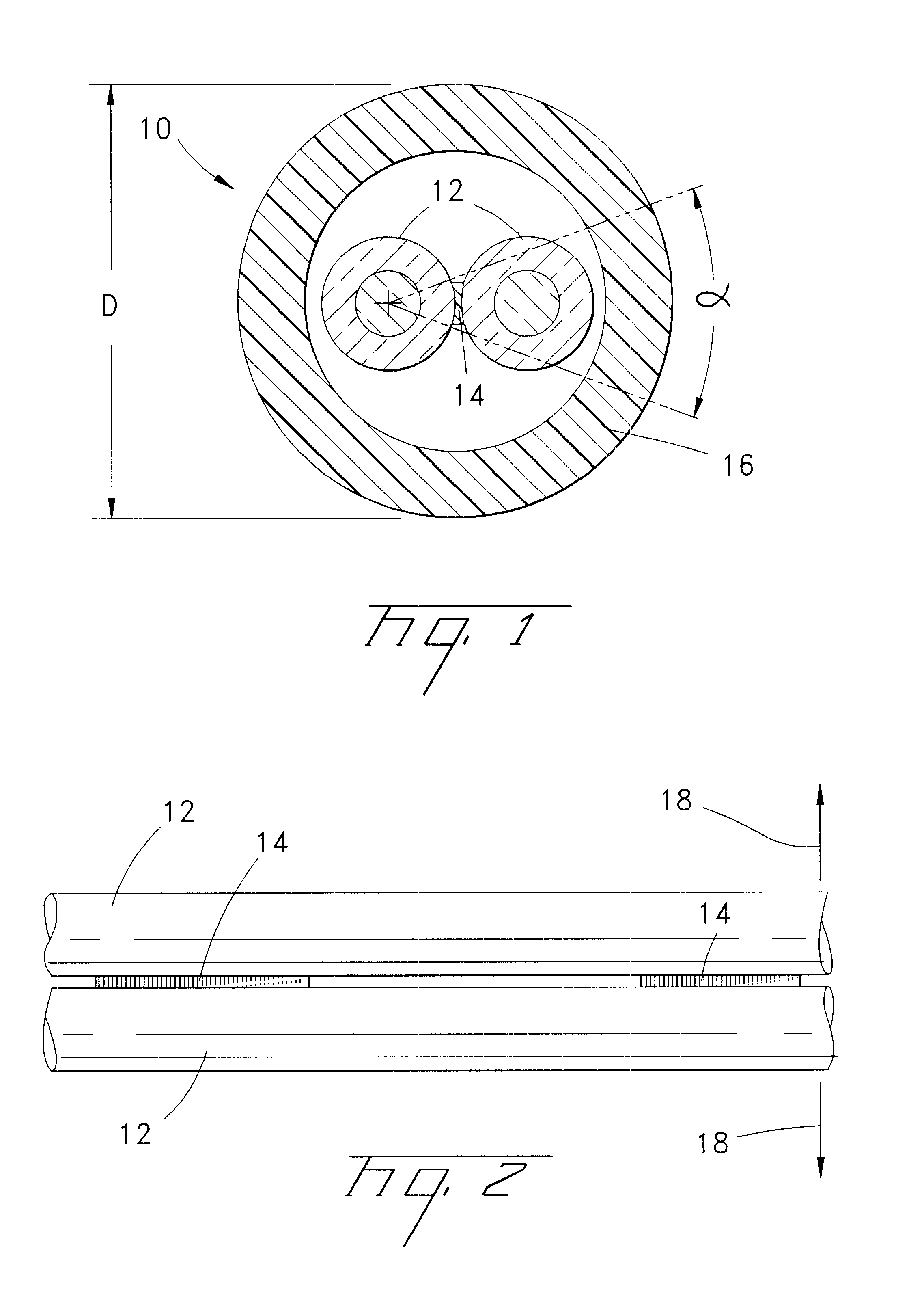
FIG. 1 depicts a cross-sectional view of an optical fiber assembly 10 in accordance with one preferred embodiment of the invention. Assembly 10 includes a pair of optical fibers 12 lightly tacked or bound together by a longitudinally continuous or intermittent colored or non-colored web 14 that is distinct from the outer layer of the optical fibers. Fibers 12 are contained within a buffer tube 16 that serves to protect the fibers. The outside diameter (OD) of tube 1...


PUM


Abstract

Optical fibers are lightly tacked together in parallel relation to prevent relative sliding between the fibers along their lengthwise directions, by forming a longitudinally extending frangible web bonded between the fibers. The web in one embodiment is formed by applying a coating of a hardenable composition in a fluid state to the adjacent fibers and then removing the composition from the fibers except on the opposing surfaces of the adjacent fibers, and causing or allowing the composition remaining between the fibers to harden. Alternatively, a coloring compound is coated onto each fiber and the fibers are pressed and held together until the compound solidifies. In yet another embodiment a solid coating of material soluble in a volatile solvent is provided on each fiber, and the coatings are contacted by solvent to render them tacky, the fibers then being pressed and held together until the coatings resolidify.

Description

FIELD OF THE INVENTIONThe present invention relates to optical fibers such as are used in fiber optic cables for communication purposes. The invention relates more particularly to a fiber optic assembly for holding two or more parallel optical fibers in desired positions with respect to one another to, for example, facilitate splicing or connectorization of the fibers.BACKGROUND OF THE INVENTIONFiber optic cables have been developed containing two or more loose optical fibers within a buffer tube. The fibers within the buffer tube are free to move in various directions relative to each other, including longitudinally along the lengthwise directions of the fibers. Connection of the optical fibers of the cable to an optical device is accomplished with the aid of a connector designed to receive ends of the fibers. One type of connector is designed to have the fiber ends inserted into a rear end of the connector and pushed through channels defined in the connector until the end faces of...

Claims


Application Information

Patent Timeline
IPC IPC(8): G02B6/44
CPCG02B6/4471G02B6/4403
Inventor HURLEY, WILLIAM C.NAVE, SAMUEL D.MOORJANI, SHAILEASTON, MARTYN
Owner CCS TECH INC
Why Eureka
Try Eureka