Contactless ignition system for internal combustion engine

a technology of contactless ignition and internal combustion engine, which is applied in the direction of automatic control of ignition, machines/engines, mechanical equipment, etc., can solve the problems of inability to realize cost reduction and shorten the life of the engin

Inactive Publication Date: 2003-07-01
OPPAMA IND
View PDF1 Cites 6 Cited by
  • Summary
  • Abstract
  • Description
  • Claims
  • Application Information

AI Technical Summary

Benefits of technology

In the present invention, at the time of startup, since ignition timing of the internal combustion engine is advanced, kick back (a phenomenon where a piston is pushed back immediately after ignition and the crankshaft rotates backwards due to piston speed being slow when starting) does not occur, and stable startup and increased speed can be expected. Also, in a normal engine speed range, it is possible to sufficiently maintain horsepower of the engine by sufficiently advancing the ignition timing. On the other hand, in a high engine speed region in excess of the normal engine speed, since the ignition timing can be retarded there is the advantage that it is possible to prevent engine overspeed.
As a preferred embodiment, it is possible for the second switching element to be a transistor that short-circuits the two ends of the trigger coil within a specified time of discharge of the trigger control condenser, to inhibit triggering of the first switching element. In this way, triggering of the first switching element can be implemented using a low cost circuit structure.
As another preferred embodiment, it is possible for the trigger control condenser to comprise a time constant circuit for determining a discharge time constant of the trigger control condenser in order to achieve ignition timing advancement control and ignition timing retardation control. In this way, there is the advantage that it is possible to select rotational speed of the engine that causes the ignition timing retardation to start easily and with high precision by setting the discharge time constant of the time constant circuit.

Problems solved by technology

However, the governor mechanism requires a large operating space because of expansion and contraction effects while rotating integrally with a crank shaft, and there is the drawback that lifespan is shortened due to mechanical operation.
Also, with an engine overspeed prevention device that uses electronic control, there is a problem that because complicated electronic circuitry is used it is not possible to realize cost reduction.

Method used


Image

  • Contactless ignition system for internal combustion engine
  • Contactless ignition system for internal combustion engine
  • Contactless ignition system for internal combustion engine

Examples


Embodiment Construction

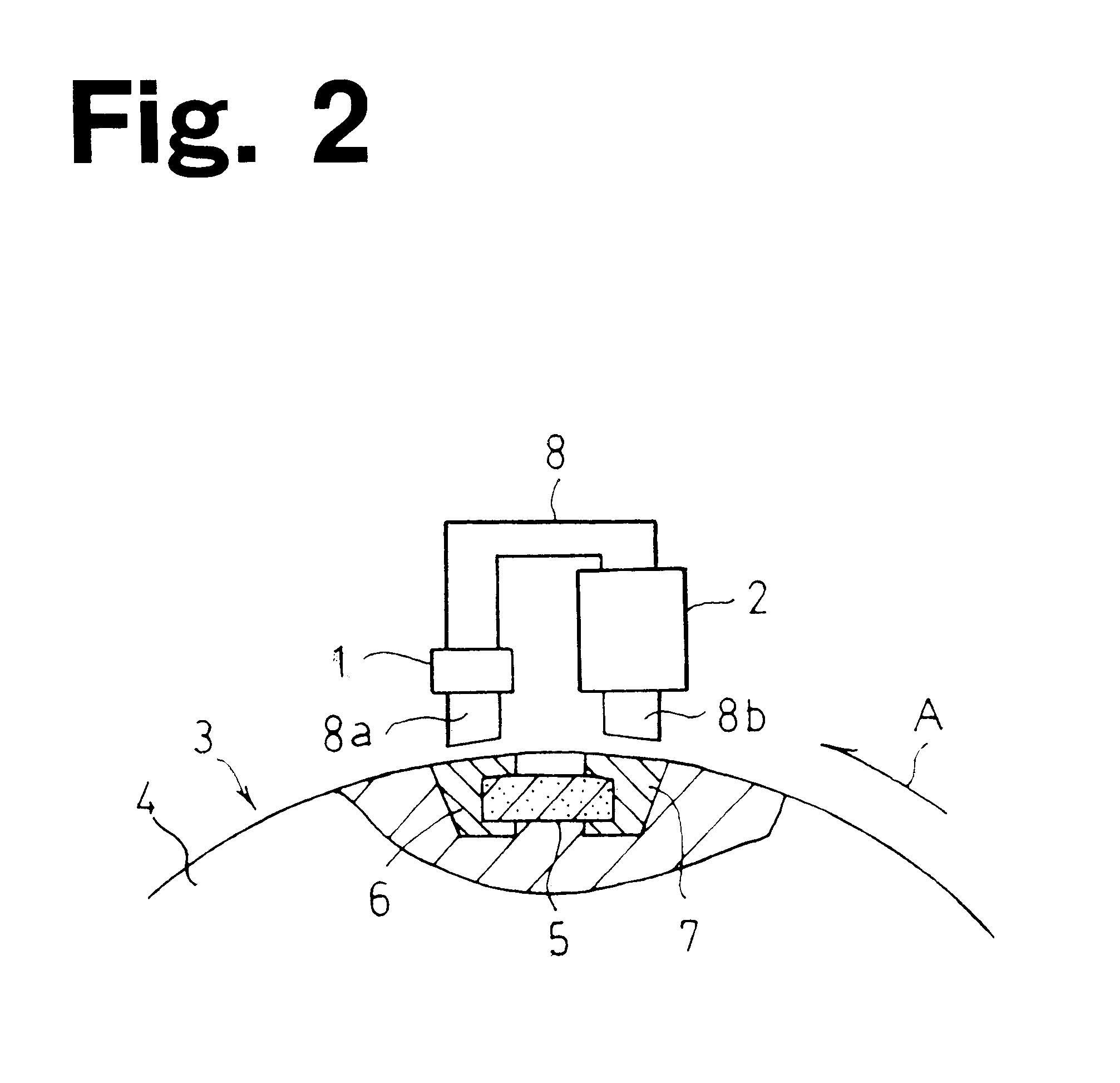
In FIG. 2, a rotor 3 constituting a contactless (non-contact) ignition system for an internal combustion engine of this embodiment has a pair of magnetic poles 6 and 7 either side of a magnet 5 embedded in a non-magnetic body 4 such as a body of aluminum, for example. Part of each of the magnetic poles 6 and 7 are exposed at an outer surface of the rotor 3, and can be made opposite to end surfaces of legs 8a, 8b of a core 8 during rotation of the rotor 3.

The core 8 is an angular U shaped-member facing the rotor 3, and a generating coil 1 and a trigger coil 2 are respectively wound around the legs 8a and 8b. Surfaces of the legs 8a and 8b opposite to the rotor 3 are formed in an arc shape so as to maintain a constant distance from the rotor 3.

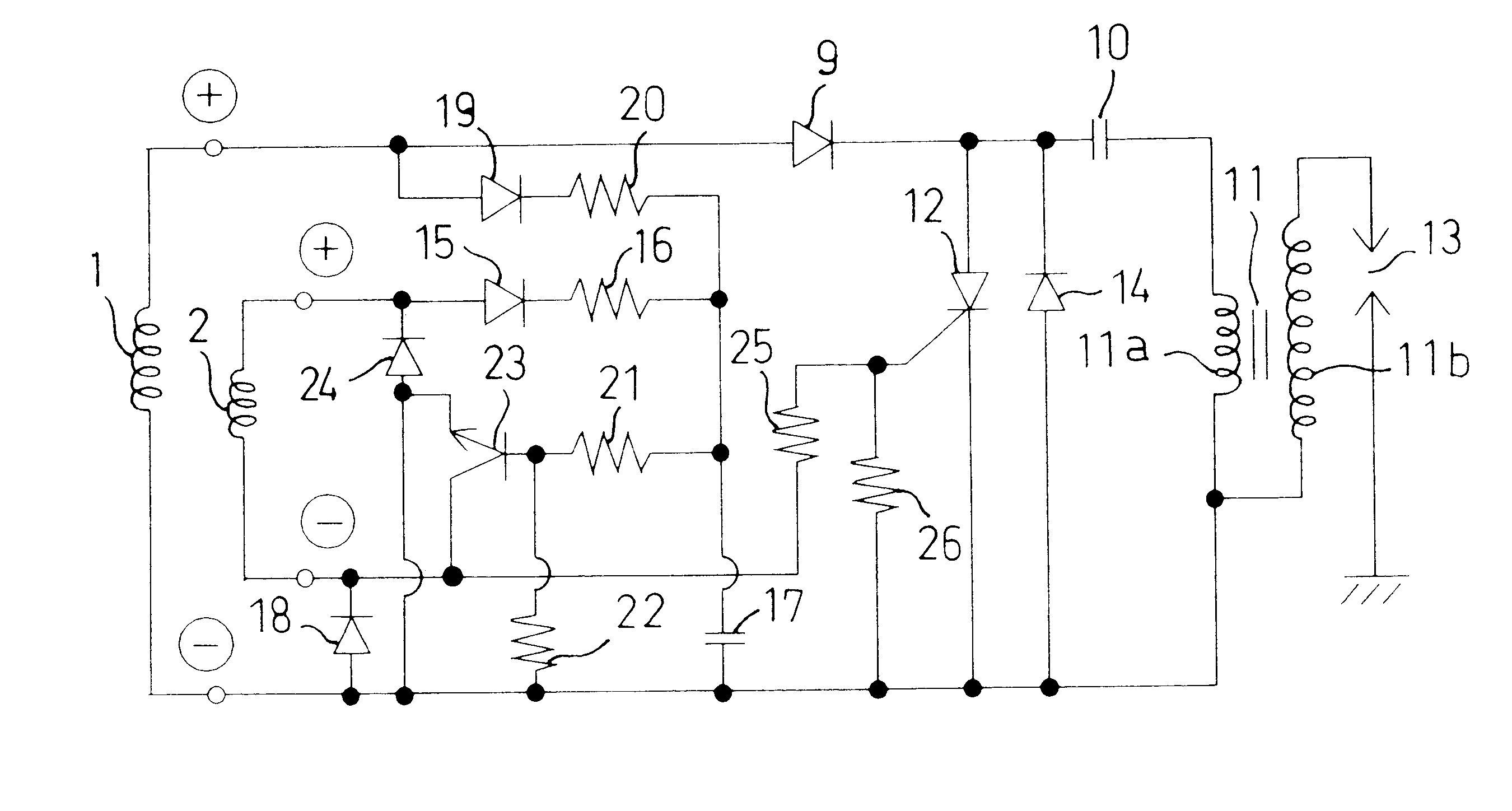
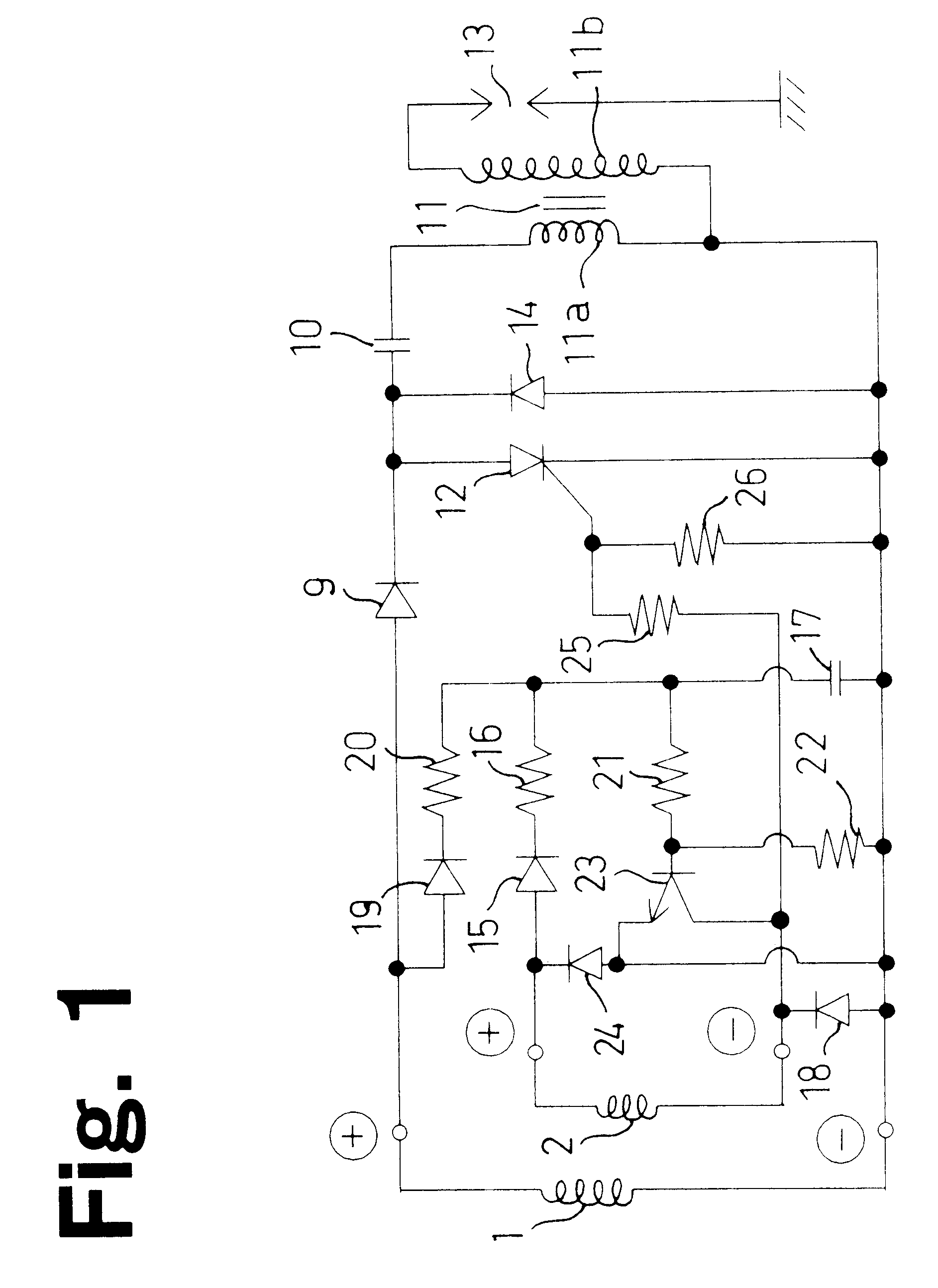
In FIG. 1, a diode 9, an ignition charge discharge condenser 10 and a primary coil 11a of an ignition coil 11 are connected in series with the generating coil 1, thus constituting a charging circuit for charging a positive voltage induced by the...


PUM


Abstract

A contactless ignition system is provided with an ignition charge discharge condenser for charging an induced voltage of a generating coil, a first switching element, triggered to conduct when an induced voltage of a trigger coil reaches an initial trigger level, for supplying a voltage charged into the ignition charge discharge condenser into an ignition coil, and a trigger control condenser for charging induced voltages of the generating coil and the trigger coil, and triggering of the first switching element caused by an induced voltage of the trigger coil is inhibited by a second switching element during a specified discharge time following charging of the trigger control condenser.

Description

1. Technical FieldThe present invention relates to a contactless (non-contact) ignition system for an internal combustion engine for automatically subjecting ignition timing to spark advance control and spark retardation control from a low rotational speed range to a high rotational speed range.2. Related ArtAs a contactless ignition system for an internal combustion engine of the related art, for example, at the time of rotation of a rotor having magnetic poles, a generating coil charges an induced voltage into an ignition charge and discharge condenser, and electrical charge charged into the ignition charge and discharge condenser is supplied to an ignition coil through switching elements that are switched by a voltage induced by a trigger coil.In this type of contactless ignition system, if the rotational speed of the internal combustion engine, namely the rotational speed of the rotor, is increased, then together with that increase in speed the charge discharge timing of the ign...

Claims


Application Information

Patent Timeline
Patent Type & Authority Patents(United States)
IPC IPC(8): F02P3/08F02P5/145F02P5/155F02P3/00F02P5/15
CPCF02P3/0838F02P3/0861F02P5/1555Y02T10/46Y02T10/40
Inventor IWATA, MASAOENOMOTO, KIYOSHIGEKITAMURA, YOSHIKISUZUKI, SHIGEYUKI
Owner OPPAMA IND
Why Eureka
Try Eureka