Voltage equalizer apparatus and method thereof

a voltage equalizer and voltage equalizer technology, applied in the direction of secondary cell servicing/maintenance, fixed transformers, transportation and packaging, etc., can solve the problems of battery discharge operation carried out by energy loss, battery may be brought into over-discharge condition, and the circuit of the whole circuit becomes complex and expensiv

Inactive Publication Date: 2003-07-01
SUBARU CORP +1
View PDF4 Cites 45 Cited by
  • Summary
  • Abstract
  • Description
  • Claims
  • Application Information

AI Technical Summary

Problems solved by technology

Such a flyback type voltage equalizer circuit necessarily requires the circuit capable of preventing the overcharge condition, and therefore, owns such a problem that the entire circuit thereof becomes complex and is manufactured in high cost.
However, the equalized voltages become the averaged voltage (correctly speaking, voltage equivalent to such a condition that battery energy is averaged) of the respective battery voltages, so that the battery voltage cannot be converged to the target voltage.
Also, since the equalizer itself does not own the charging function, when the equalizing operation is continued, the discharge operation of the battery is carried out by the energy loss consumed by this equalizer.
As a result, there is a risk that the battery may be brought into the over discharge condition.

Method used


Image

  • Voltage equalizer apparatus and method thereof
  • Voltage equalizer apparatus and method thereof
  • Voltage equalizer apparatus and method thereof

Examples


second embodiment

FIG. 3 is a diagram for indicating a voltage equalizing circuit according to the present invention.

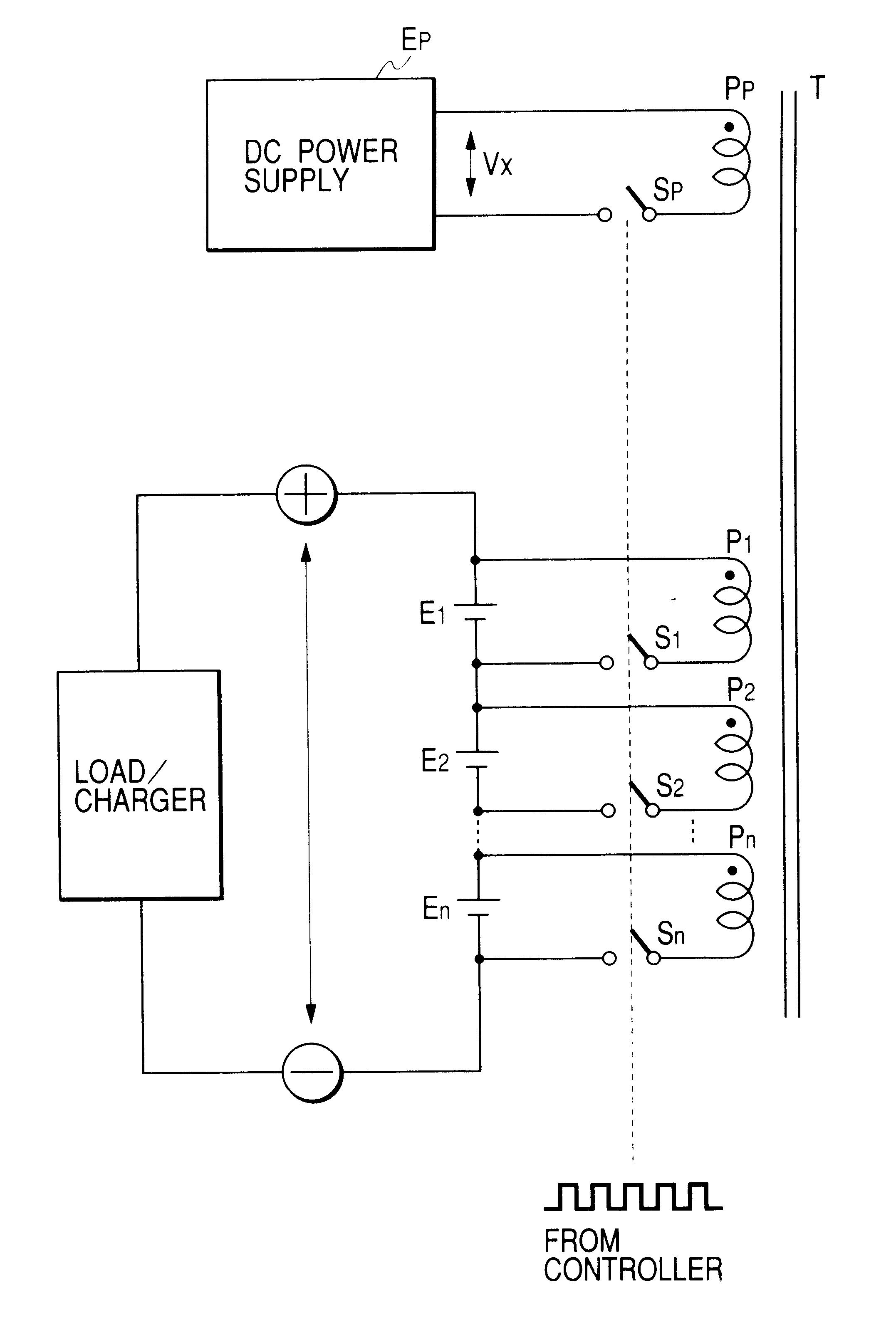
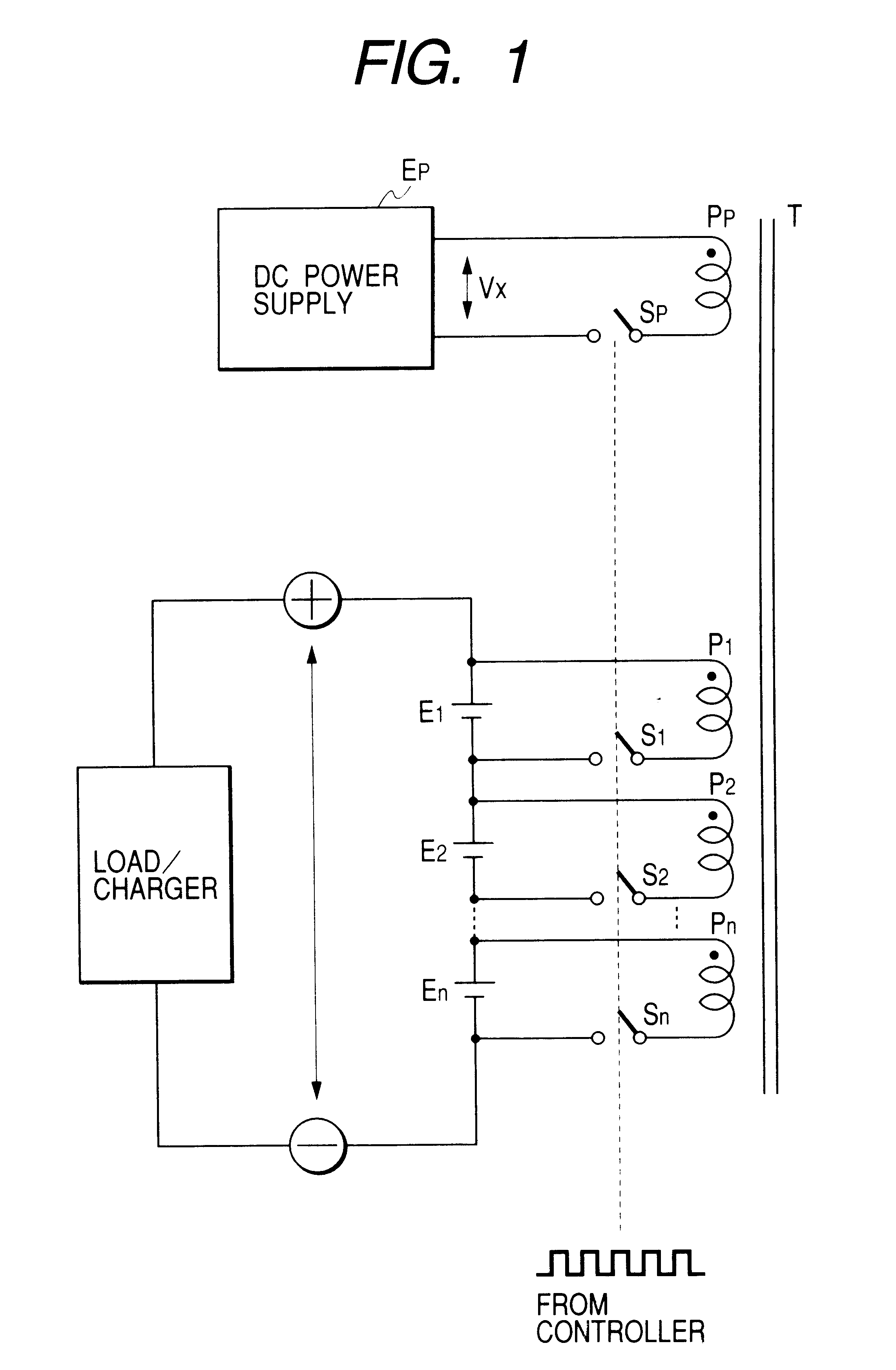
In FIG. 3, reference numerals P1 to Pn show a plurality of windings which are electromagnetically coupled to each other by a transformer T. Reference numerals S1 to Sn indicate a plurality of first switching elements. Reference numbers E1 to En represent storage elements which are series-connected to each other. These storage elements are constituted by such storage elements as batteries, electric double layer capacitors, or the like. Each of these first switching elements S1 to Sn, each of these windings P1 to Pn, and each of these storage elements E1 to En are series-connected to each other, so that a plurality of closed circuits are arranged. Also, series-connecting terminals "+" and "-" of the plural storage elements E1 to En series-connected to each other are connected to an external charging circuit and / or a load.

Also, reference numeral "Pp" shows a reference voltage winding whic...

third embodiment

FIG. 4 is a diagram for indicating a voltage equalizing circuit according to the present invention.

In FIG. 4, reference numerals P1 to Pn show a plurality of windings which are electromagnetically coupled to each other by a transformer T. Reference numerals S1 to Sn indicate a plurality of first switching elements. Reference numbers E1 to En represent storage elements which are series-connected to each other. These storage elements are constituted by such storage elements as batteries, electric double layer capacitors, or the like. Each of these first switching elements S1 to Sn, each of these windings P1 to Pn, and each of these storage elements E1 to En are series-connected to each other, so that a plurality of closed circuits are arranged. Also, series-connecting terminals "+" and "-" of the plural storage elements E1 to En series-connected to each other are connected to an external charging circuit and / or a load.

Also, reference numeral "Pp" shows a reference voltage winding whic...

fourth embodiment

FIG. 5 is a diagram for indicating a voltage equalizing circuit according to the present invention.

In FIG. 5, reference numerals P1 to Pn show a plurality of windings which are electromagnetically coupled to each other by a transformer T. Reference numerals S1 to Sn indicate a plurality of first switching elements. Reference numbers E1 to En represent storage elements which are series-connected to each other. These storage elements are constituted by such storage elements as batteries, electric double layer capacitors, or the like. Each of these first switching elements S1 to Sn, each of these windings P1 to Pn, and each of these storage elements E1 to En are series-connected to each other, so that a plurality of closed circuits are arranged. Also, series-connecting terminals "+" and "-" of the plural storage elements E1 to En series-connected to each other are connected to an external charging circuit and / or a load.

Also, reference numeral "Pp" shows a reference voltage winding whic...


PUM

PropertyMeasurementUnit
voltageaaaaaaaaaa
voltageaaaaaaaaaa
poweraaaaaaaaaa

Abstract

In such a voltage equalizer circuit in which each of plural windings P1 to Pn electromagnetically coupled to each other, each of plural storage elements E1 to En series-connected to each other, and each of plural first switching elements S1 to Sn are connected to each other in a series connecting manner so as to constitute a plurality of closed circuits, this voltage equalizer apparatus is featured by that a reference voltage winding Pp electromagnetically coupled to the plurality of windings is provided; both a DC power supply Ep and a second switching element Sp are series-connected to the second winding; and all of the plural first switching elements and the second switching element are turned ON / OFF in a synchronous manner.

Description

1. Field of the InventionThe present invention relates to a technique capable of equalizing voltages across both terminals of the respective series-connected storage elements in such a manner that energy is transferred among a plurality of series-connected storage elements which are mounted on an electric automobile, an energy-hybrid type vehicle, and various sorts of systems capable of using storages of electric energy.2. Description of the Related ArtJapanese Laid-open Patent Application No. Hei-8-214454 and U.S. Pat. No. 5,594,320 discloses voltage equalizer circuits.Generally speaking, a voltage equalizer circuit disclosed in these publications is referred to as a "flyback type voltage equalizer circuit." As indicated in FIG. 8, the flyback type voltage equalizer circuit is equipped with a transformer having a plurality of secondary windings n2 to n4; a switch SW1 connected to a primary winding n1 of this transformer T1; a plurality of rectifying circuits CR1, CR2, CR3 connected...

Claims


Application Information

Patent Timeline
Patent Type & Authority Patents(United States)
IPC IPC(8): H02J7/00H02J7/02H01M10/44H02J1/00H02M3/28
CPCH02J7/0016Y02T10/7055Y02T10/70
Inventor MATSUI, FUJIOISHII, MITSUNORIANZAWA, SEIICHINISHIZAWA, HIROSHI
Owner SUBARU CORP
Why Eureka
Try Eureka