Hollow rack shaft

a rack shaft and hollow technology, applied in the direction of hoisting equipment, gearing, transportation and packaging, etc., can solve the problems of unnecessarily thick thickness, low strength of the rack teeth, and insufficient lightness of the rack sha

Inactive Publication Date: 2003-07-08
NSK LTD
View PDF15 Cites 18 Cited by
  • Summary
  • Abstract
  • Description
  • Claims
  • Application Information

AI Technical Summary

Problems solved by technology

The metal flow is cut off when the portions of the work piece are removed in the gear cutting process, therefore the rack teeth have low strength.
However, in this method, the work piece whose thickness (volume) is equal to the total volume of the rack teeth and the rack teeth bottom portion is required, thus the thickness except the rack teeth portion is unnecessarily thick.
This causes a problem that the rack shaft could not be made sufficiently light.
However, this Japanese Laid-Open Patent does not disclose how to optimize the uneven shape of the rack tooth back surface in order to prevent the stress concentration, nor what metal flow is optimum in the vicinity of the rack teeth.
Generally, it is very difficult to form a wave-like unevenness on the inner surface of a hollow work piece by inserting a mandrel having a complementary surface to the unevenness.
Because the mandrel is necessary to be thin or slender enough to press into the hollow and therefore can not endure the lateral force for forming.
This means that a volume of material at each point along the axis of the rack teeth row is changed and therefore it is difficult to form a row of rack teeth with precision without arch deformation.
Since stress in the vicinity of point b1 hardly appears, it is possible to say that the material in the vicinity of point b1 causes an unnecessary increase of the rack shaft weight.

Method used


Image

  • Hollow rack shaft
  • Hollow rack shaft
  • Hollow rack shaft

Examples


second embodiment

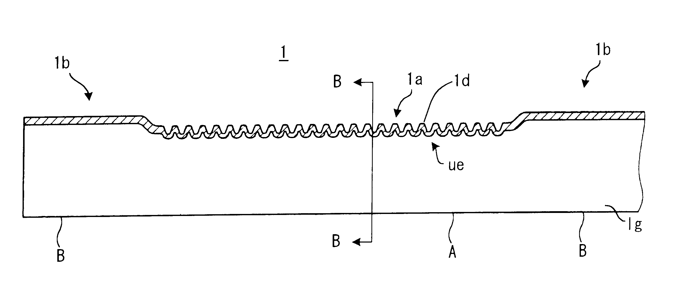
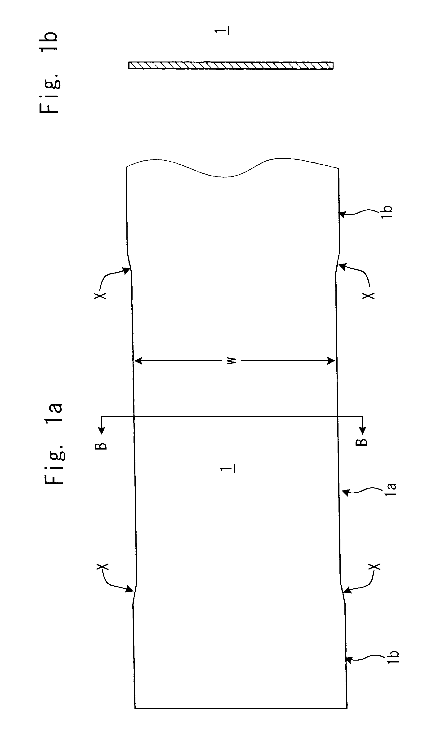
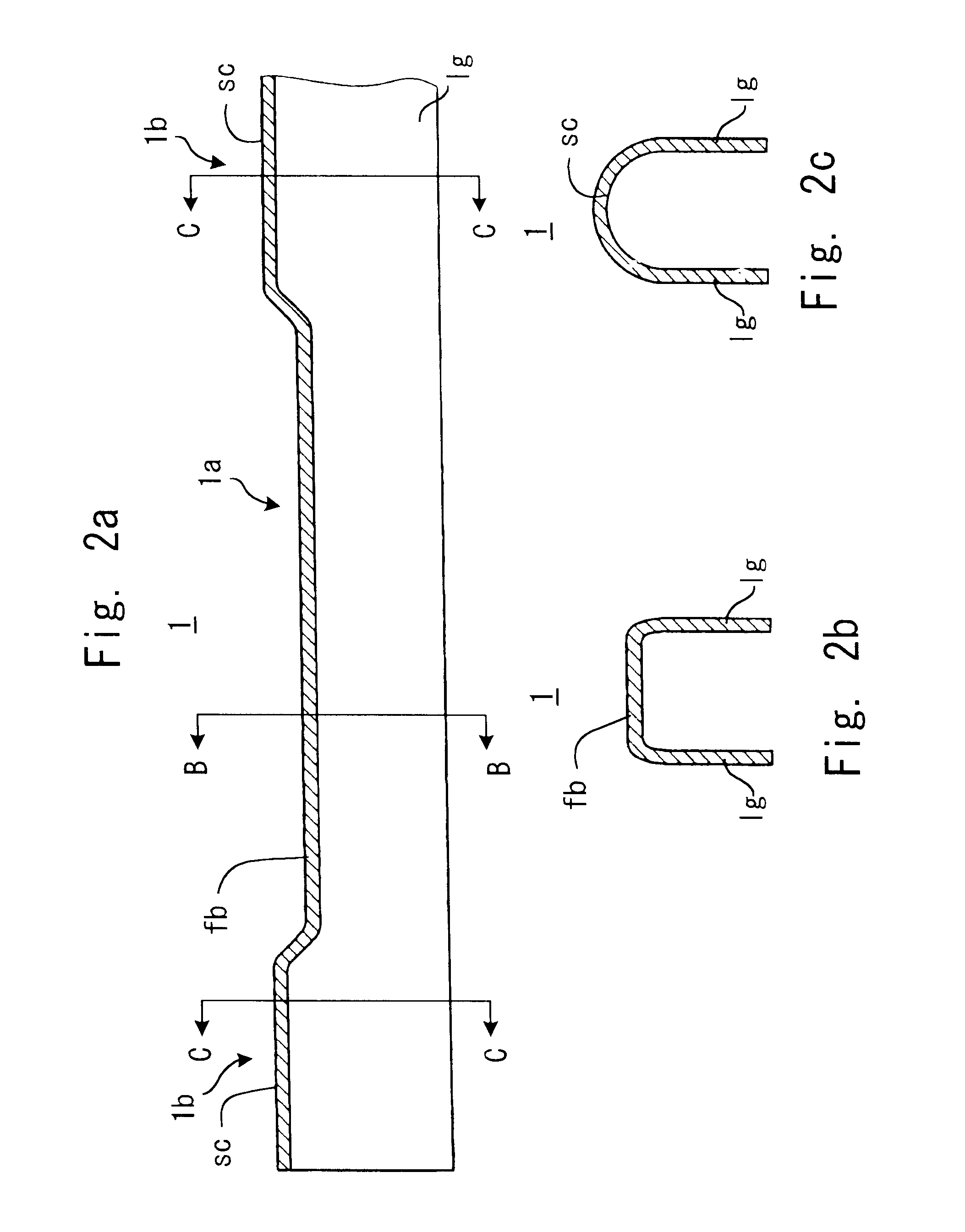
FIG. 10 is a perspective view for describing in a simple manner the method for manufacturing a hollow rack shaft utilizing plural work pieces. In the first process, an upper gutter-like work piece 22 with rack teeth to comprise upper half (rack teeth side) of the hollow rack shaft is formed from a solid cuboid work piece 21 or a plate work piece. The gutter-shaped work piece 22 is essentially the same as that of the first embodiment except for the difference of the leg length. The lower die approaches from between the two open legs, and as related above, the unevenness ue are formed on the surface IS on the back of the rack teeth row. In the second process of this embodiment, a semicircular lower gutter-like work piece 23 formed from cuboid work piece 21 or a plate work piece, is welded to the upper gutter-like work piece 22. The welded section and both ends are then finished by grinding.

In this embodiment, the two gutter-shaped work pieces are welded at approximately symmetric posi...

third embodiment

FIG. 11 is a perspective view for showing in a simple manner another method for manufacturing a hollow rack shaft utilizing plural work pieces. A four-cornered hollow rack shaft is shown because a circular shape is not always required for both ends of the hollow rack shaft. In the first process, an upper gutter-like work piece 22 with rack teeth to comprise the upper half (rack teeth side) of the hollow rack shaft is formed from a solid cuboid work piece 21 or a plate workpiece. The gutter-like work piece 22 is essentially the same as that of the first embodiment and the gutter-like work piece of the second embodiment except for the difference of the leg length, and as previously described, the lower die approaches through between the two open legs, and the unevenness ue are formed on the surface IS on the back of the rack teeth row. In the second process of this embodiment, a separately prepared lower plate piece 24 is welded to the gutter-like work piece 22. The welded section and...


PUM


Abstract

A hollow rack shaft is produced by forming a plate work piece and has continuous metal flow along the contour of rack teeth surface without being cut. A series of wave-like concave-convex sections is formed on the inner surface of the shaft. Thickness of tooth body and tooth bottom of the rack teeth is adjusted by dimensions of the unevenness. Thereby, stress concentration at each point of the rack shaft is prevented and the shaft is strengthened and its weight reduced.

Description

This application is based on applications No. 2000-114340 and 2000-145833 filed in Japan, the contents of which are hereby incorporated for reference.1. Field of the InventionThis invention relates to a hollow rack shaft for a steering apparatus used in automobiles.2. Description of the Related ArtA rack-and-pinion type steering apparatus is frequently used in automobiles. Rotation of the steering wheel by the driver is transmitted to a pinion meshed with a rack shaft. The rack shaft is connected to a steering rod for controlling the front wheels. The driver can therefore control the direction the automobile moves by rotating the steering wheel. The steering mechanism as described above is well known in the related art so further explanation is omitted here.In the prior art, rack teeth have been obtained by gear cutting from a solid rod work piece. In the original steel bar for the workpiece, longitudinal metal flow is formed along the rolling direction. An anisotropy in strength be...

Claims


Application Information

Patent Timeline
Patent Type & Authority Patents(United States)
IPC IPC(8): B21K1/76B21K1/00B62D3/00B62D3/12F16H55/02F16H55/26
CPCB21K1/767B21K1/768F16H55/26B62D3/126Y10T74/19949Y10T74/1967
Inventor TSUBOUCHI, AKIRAOKUBO, KIYOSHIWATANABE, YASUSHI
Owner NSK LTD
Why Eureka
Try Eureka