Method and apparatus for improving the interrogation range of an RF-Tag

a technology of rf tag and interrogation range, which is applied in the field of wireless communication systems using backscatter, can solve the problems of weak signals returned from rf tags and notably more limited interrogation range of rf tags

Inactive Publication Date: 2003-07-08
LGS INNOVATIONS +1
View PDF3 Cites 52 Cited by
  • Summary
  • Abstract
  • Description
  • Claims
  • Application Information

AI Technical Summary

Problems solved by technology

However, many modulation schemes are possible such for example, as Phase Shift Keying (PSK) of the subcarrier (e.g., BPSK, QPSK), more complex modulation schemes (e.g., MSK, GMSK), etc.
The advantages of using RF Tags to transmit information to an Interrogator are accompanied by a disadvantage: since the RF Tag is only a reflector, the signals returned from it are generally weaker than in systems that generate RF energy at both ends of the communications link.
Thus, the interrogation range of the RF Tag is notably more limited by its distance from the RF transmitting source.

Method used


Image

  • Method and apparatus for improving the interrogation range of an RF-Tag
  • Method and apparatus for improving the interrogation range of an RF-Tag
  • Method and apparatus for improving the interrogation range of an RF-Tag

Examples


Embodiment Construction

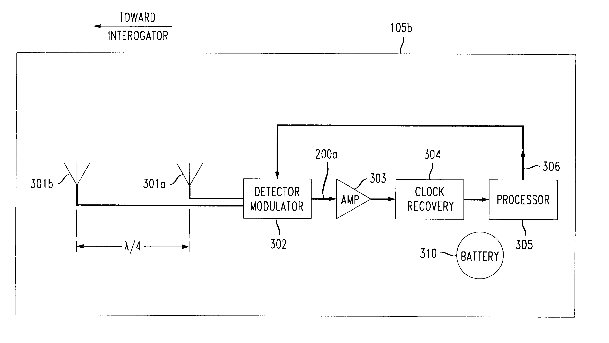
Referring now to FIGS. 3B and 6A, in accordance with an embodiment of the present invention an RF Tag 105b includes a first antenna (reflecting) element 301a and a second antenna (reflecting) element 301b predeterminately disposed with respect to the first reflecting element 301a such that the echo signal of second reflecting element 301b is preferably 180.degree. out of phase with the echo signal generated by first reflecting element 301a. This phase relationship can be achieved by positioning the second reflecting element 301b a distance of approximately one-quarter wavelength (.lambda. / 4) from the first reflecting element 301a and then orienting the RF Tag so the axis of the two reflecting elements points towards the Interrogator. The axial alignment of the two reflecting elements in the direction of the expected incident radiation (i.e., the direction from which the Interrogator interrogates the RF Tag) is required to achieve the 180.degree. phase relationship and therefore a co...


PUM


Abstract

A method for increasing the interrogation range of an RF Tag in a radio communication system using RF Tags with multiple reflecting antenna elements. The reflecting antenna elements are predeterminately positioned, and preferably aligned, with respect to each other in the direction of expected incident RF radiation. The reflecting antenna elements are sequentially pulsed on and off such that while the first reflecting antenna element is in a signal reflecting operating state, the remaining reflecting antenna elements are in a substantially non-reflecting state, and when the second reflecting element is in a reflecting operating state, the remaining reflecting elements are in a non-reflecting state, etc. The sequential pulsing and predetermined fixed spacing between the reflector elements generates constructive interference between the reflected signals of the reflecting antenna elements which increases the power of the resulting reflected signal.

Description

BACKGROUND OF THE INVENTION1. Field of the InventionThe present invention relates to wireless communication systems and, more particularly, wireless communication systems using backscatter technology.2. Description of the Related ArtRF Tag systems are radio communication systems that communicate between a radio transceiver, called an Interrogator, and a number of inexpensive devices denoted as Tags. In RF Tag systems, the Interrogator communicates to the Tags using modulated radio signals which activate any Tag in range or may activate a specific Tag within the range. After activating a Tag, the Interrogator may transmit information to it (this is called the Downlink). The Interrogator transmits a Continuous-Wave (CW) radio signal to the Tag; the Tag then modulates the CW signal using modulated backscattering (MBS) in which the Tag is electrically switched by the modulating signal, from being an absorber of RF radiation to a reflector of RF radiation. This modulated backscatter allo...

Claims


Application Information

Patent Timeline
Patent Type & Authority Patents(United States)
IPC IPC(8): G08B13/24G06K7/00H01Q21/29H01Q21/00
CPCG06K7/0008G08B13/2417G08B13/2462G08B13/2471G08B13/2488H01Q21/29
Inventor HELMS, HOWARD DAVID
Owner LGS INNOVATIONS
Why Eureka
Try Eureka