Double-walled grow light housing with air flow cooling system

a technology of air flow and cooling system, which is applied in the direction of fixed installation, transportation and packaging, lighting and heating equipment, etc., can solve the problems of low light intensity, high temperature injurious, and temperature below the optimal in the area around plants

Inactive Publication Date: 2003-07-22
HYDROFARM LLC
View PDF2 Cites 169 Cited by
  • Summary
  • Abstract
  • Description
  • Claims
  • Application Information

AI Technical Summary

Problems solved by technology

However, high intensity lights generate considerable heat that can create injurious high temperatures in the immediate vicinity of the plants under the high intensity light.
Facility-wide cooling systems may employed to this end, but such systems are costly and, if operated to cool plants under the high intensity lights, may result in temperatures below optimum in the areas around plants under low intensity lighting.

Method used


Image

  • Double-walled grow light housing with air flow cooling system
  • Double-walled grow light housing with air flow cooling system
  • Double-walled grow light housing with air flow cooling system

Examples


Embodiment Construction

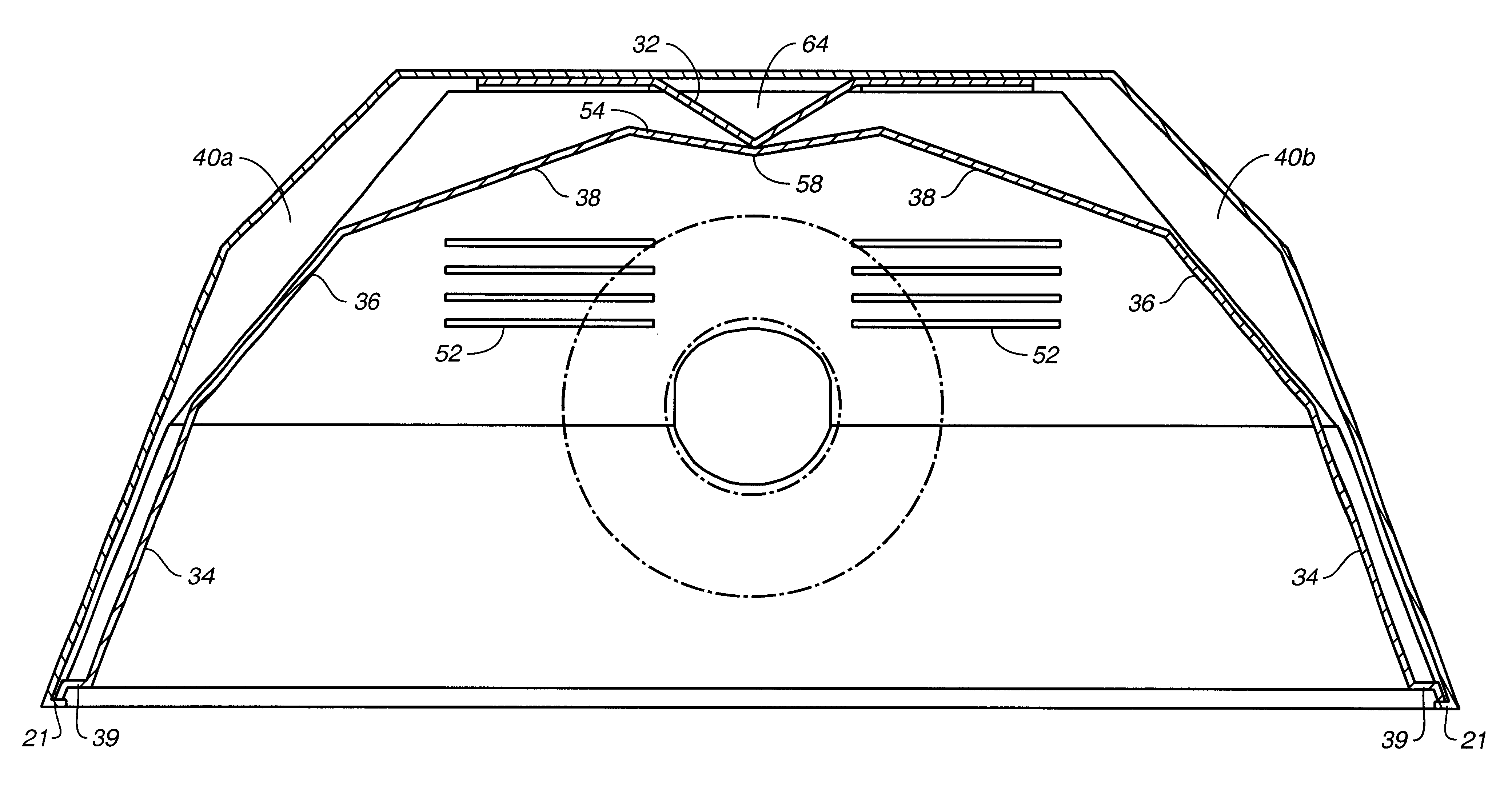
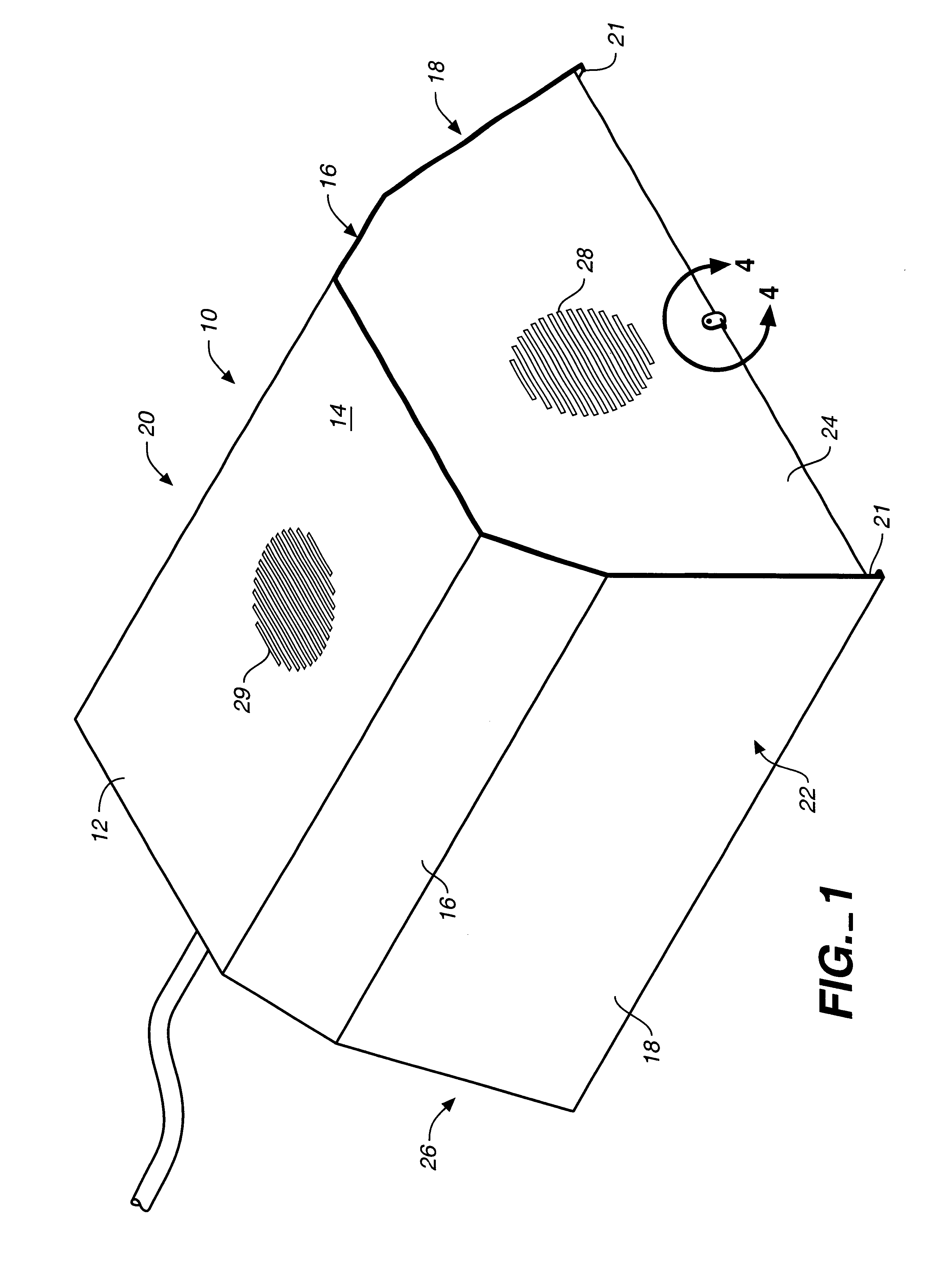
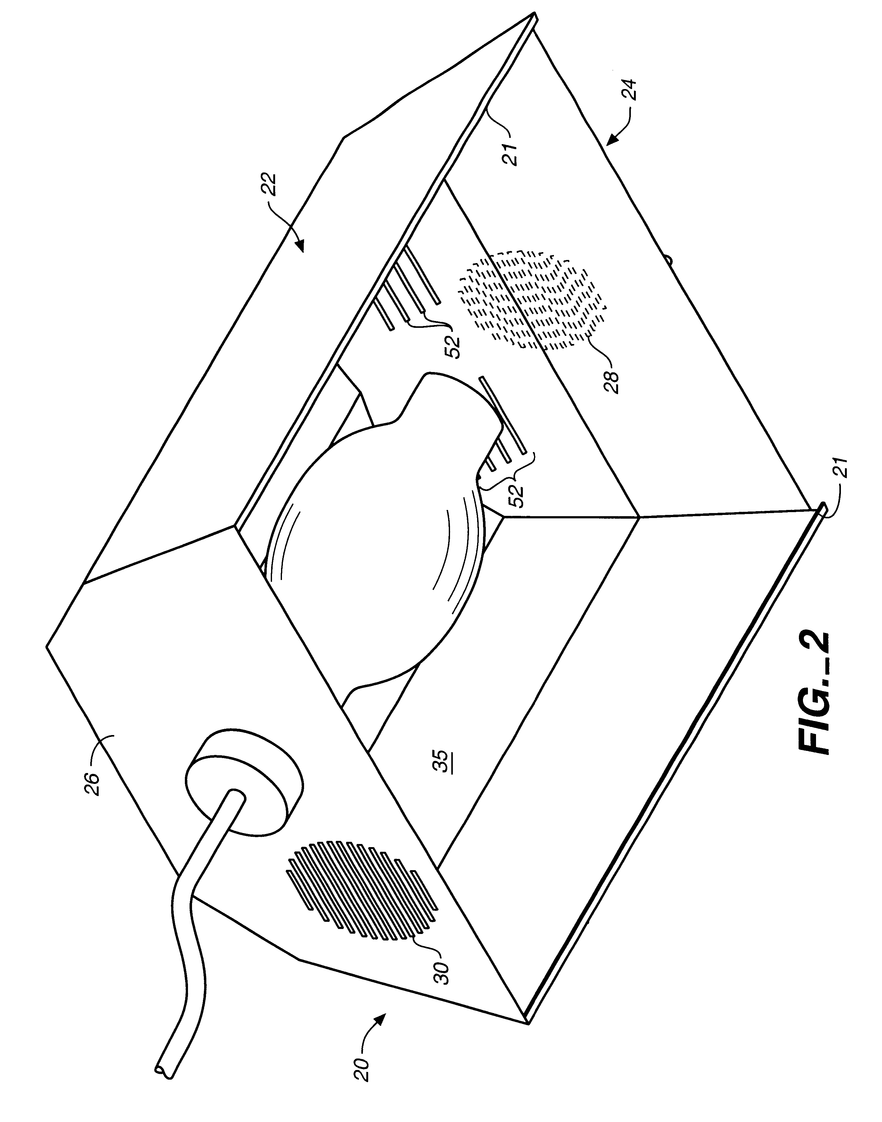
Referring to FIGS. 1 through 14, wherein like reference numerals refer to like components in the various views, FIG. 1 is an upper front perspective view of the doubled-walled grow light housing with air flow air cooling system of the present invention, generally denominated 10 herein. FIG. 2 is a lower rear perspective view of the light housing of FIG. 1, showing the interior structures and air flow ports, while FIG. 3 is an exploded perspective view showing the exterior housing shell, specular positioning device, and specular interior insert. FIG. 4 is a detailed view of the glass retention tab which secures the glass covering or lens within the housing. FIG. 5 is a bottom view of the grow light housing and FIG. 6 is a rear cross-sectional elevation view taken along section lines 6--6 as shown in FIG. 5. FIG. 7 is a left side cross-sectional view in elevation of the grow light housing as viewed along section lines 7--7 in FIG. 5.

These views collectively show that the housing 10 ge...


PUM


Abstract

A grow light having an exterior shell with an air inlet and a hot air exhaust outlet, and a specular interior insertable into the shell. The sides of the specular insert are spaced apart from the walls of the shell so as to form a double-walled housing having air cooling chambers and vents which facilitate the movement and exhaust of air heated by high intensity light bulbs.

Description

Not applicable.Not applicable.REFERENCE TO A MICROFICHE APPENDIXNot applicable.The present invention relates generally to horticultural and agricultural lighting systems for use in growing plants indoors, and more particularly to a double-walled grow light housing having an integral air flow cooling system that may be either active or passive.DISCUSSION OF RELATED ARTIndoor hydroponic and soil-based plant growing systems have evolved to become indispensable tools in both horticulture and agriculture. Each system includes, as essential elements, plant nutrient media and containers for such, climate control, lighting, and hydration. Large or full-sized plants, and those indigenous to latitudes and growing regions characterized by intense sunlight, frequently require high intensity lights for optimal growing conditions. However, high intensity lights generate considerable heat that can create injurious high temperatures in the immediate vicinity of the plants under the high intensity l...

Claims


Application Information

Patent Timeline
Patent Type & Authority Patents(United States)
IPC IPC(8): F21V29/02F21V29/00
CPCA01G7/045A01G9/26F21V29/02A01G9/249F21V29/83F21S8/02Y02P60/14Y02A40/25
Inventor WARDENBURG, PETER
Owner HYDROFARM LLC
Why Eureka
Try Eureka