Rotor with elastic diaphragm defining a liquid separating chamber of varying volume

a rotor and diaphragm technology, applied in the field of blood processing systems, can solve the problems of large diaphragm diameter, large extracorporeal volume, complicated setup and use,

Inactive Publication Date: 2003-08-05
HAEMONETICS
View PDF73 Cites 51 Cited by
  • Summary
  • Abstract
  • Description
  • Claims
  • Application Information

AI Technical Summary

Problems solved by technology

Although continuous-flow systems have the advantage that the amount of blood that must be outside the donor or patient can be relatively small, they have the disadvantage that the diameter of the rotor is large.
These systems are, as a consequence, large; furthermore, they are complicated to set up and use.
Discontinuous-flow systems have the advantage that the rotors are relatively small in diameter but have the disadvantage that the extracorporeal volume is large.
This, in turn, makes it difficult or impossible to use discontinuous systems on people whose size and weight will not permit the drawing of the amount of blood required to fill the rotor.
Because the bowls in these systems are rigid and have a fixed volume, however, it is difficult to control the hematocrit of the final product, particularly if the amount of blood salvaged is insufficient to fill the bowl with RBCs.
It has the advantage of being able to vary the volume of the rotor to control the final hematocrit but has the disadvantage of being limited to a rather flat, wide pancake-like shape due to manufacturing constrictions.
The Cobe system takes up a fairly large amount of space, and its flexible pancake-shaped rotor is awkward to handle.
The Cobe system does not permit blood to flow into and out of its rotor at the same time.
The Cobe system also does not permit blood to be pulled into the rotor by suction.
Because of their cost and complexity of use, these systems are used only in operations where relatively large blood loss is expected.
The prior-art rotors used for processing blood collected during an operation, made by Haemonetics Corp. and others, must be completely filled with RBCs before any processing can occur, and thus the process takes more time and is not appropriate for use with small people or for an operation with low blood loss.
Because the volume of the processing chamber is fixed, the final concentration of the RBCs in the last cycle of the process cannot be easily controlled.
This wound-drain system has the disadvantage that the blood returned to the patient contains, in addition to the RBCs, substances that may be deleterious to the patient.

Method used


Image

  • Rotor with elastic diaphragm defining a liquid separating chamber of varying volume
  • Rotor with elastic diaphragm defining a liquid separating chamber of varying volume
  • Rotor with elastic diaphragm defining a liquid separating chamber of varying volume

Examples


Embodiment Construction

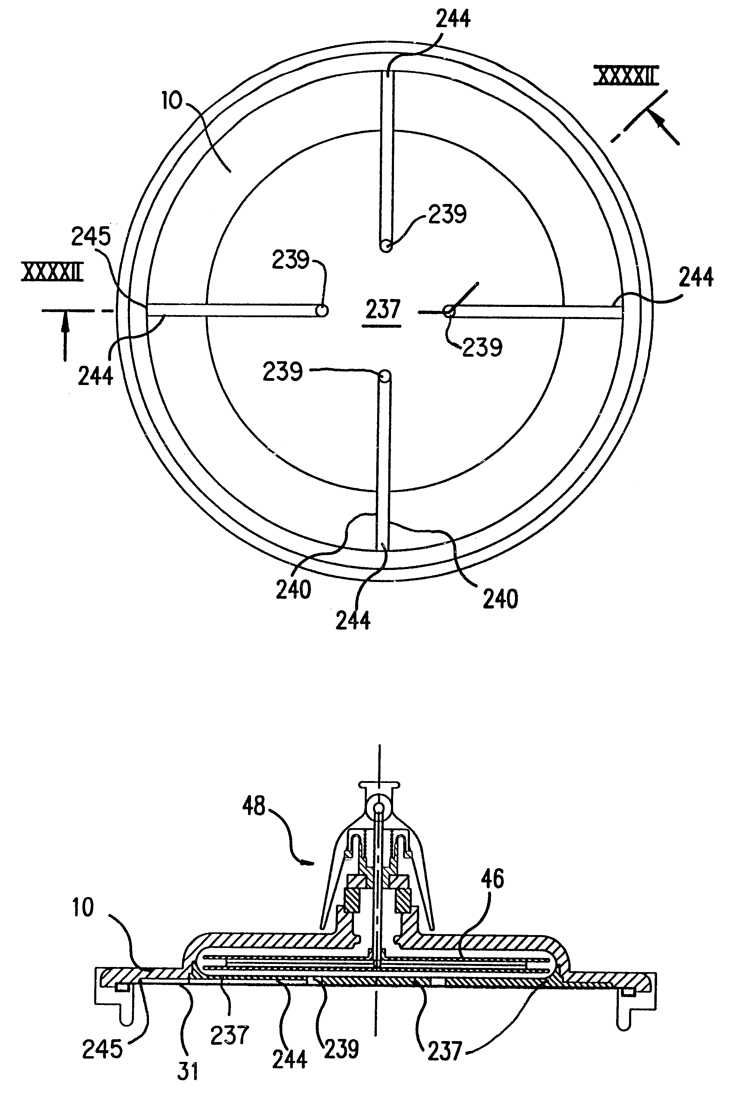
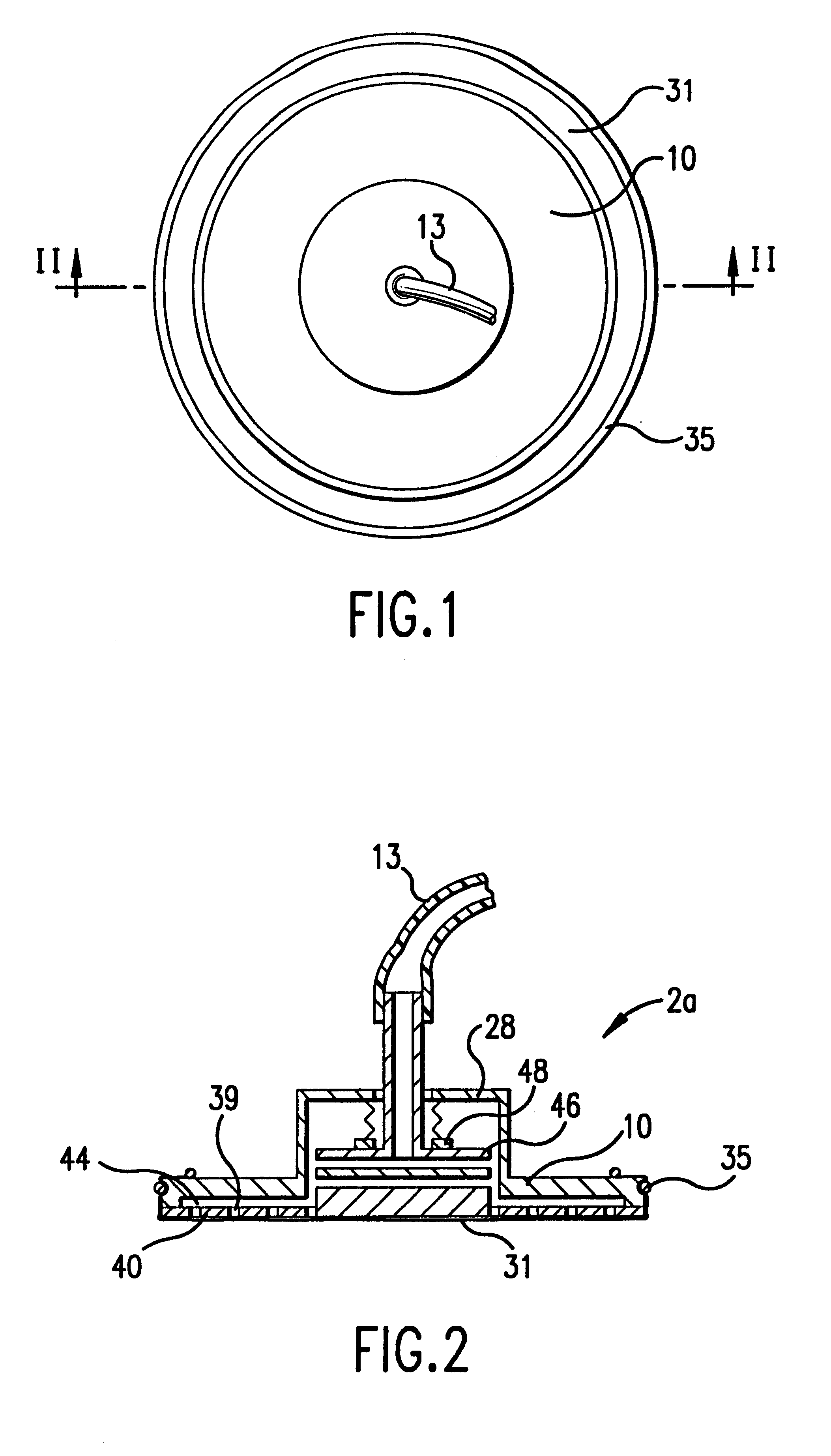
FIGS. 1 and 2 show a version of the centrifuge rotor 2a according to the present invention. The rotor 2a has an elastic boundary, i.e., an impermeable diaphragm 31, which is sealed to a rigid, imperforate boundary wall 10 by an O-ring 35 or other means. The diaphragm 31 is preferably made of an elastic, stretchable and resilient material, such as latex or silicone rubber. A perforate interior wall 40--also referred to as a plate--having holes 39 is attached under the rigid boundary wall 10. Preferably, the boundary wall 10 and the interior wall 40 are made out of a rigid thermoplastic. The perforate interior plate 40 is held a short distance away from the imperforate boundary wall 10 by standoffs (not shown), thereby forming a passage 44.

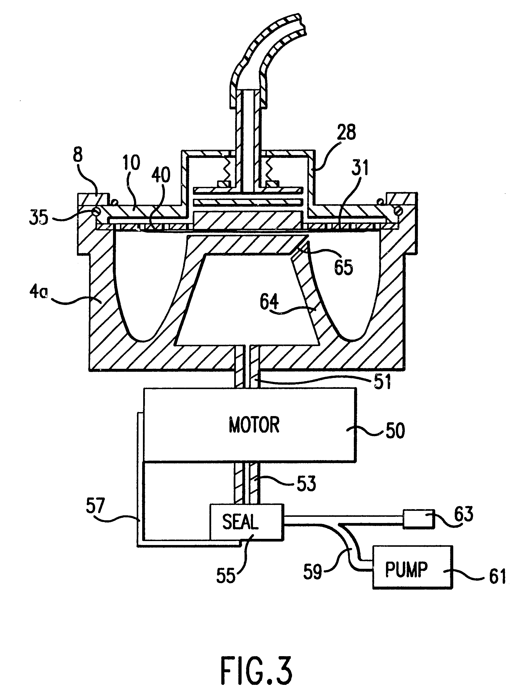
The rotor 2a also has a collector assembly 46, which is attached to tube 13, and a rotary seal 48, which maintains the sterile environment in the rotor 2a but allows the rotor to turn even while the collector assembly is held stationary. The rotary ...


PUM


Abstract

A rotor for collecting and centrifuging biological fluids in a range of volumes. The rotor includes an elastic impermeable diaphragm which defines at least a portion of a variable-volume processing chamber, where the fluid is centrifuged. The rotor includes a rigid mounting member, to which the diaphragm is mounted and which is held and spun by a chuck. Preferably, this rigid mounting member includes a boundary wall which together with the elastic diaphragm defines the chamber. The boundary wall may be a substantially imperforate circular wall which extends to the periphery of the processing chamber but defining one opening, preferably near the axis of rotation, permitting a conduit or conduits to pass therethrough so as to be in fluid communication with the processing chamber. The rotor may include a separate structure for controlling the flow of liquid out of the chamber into the conduit. In a preferred embodiment, this outlet-control structure is a perforate, substantially rigid wall or plate, located within the processing chamber and mounted adjacent the rigid boundary wall. In an alternative embodiment, the outlet-control structure for controlling flow from the processing chamber to the conduit may include at least one tube or preferably a set of tubes, wherein each tube provides fluid communication between the chamber and the conduit. In one preferred embodiment, grooves in the boundary wall may be used as the outlet-control structure.

Description

DESCRIPTION1. Technical FieldThis invention generally relates to systems for processing blood and other biological fluids.2. Background ArtCentrifugal biological-fluid-processing systems have been in existence for some time. Some are used to collect high concentrations of certain components of a person's blood while others are used to further process blood components by washing, concentrating or otherwise purifying the blood component of interest. Some of these systems are used to process biological fluids other than blood. Filtration systems are also used for processing blood and other biological fluids.The centrifugal systems (hereinafter called blood-processing systems) generally fall into two categories, continuous-flow devices and discontinuous-flow devices.In continuous-flow systems, whole blood from the donor or patient flows through one conduit into the spinning rotor where the components are separated. The component of interest is collected and the unwanted components are r...

Claims


Application Information

Patent Timeline
Patent Type & Authority Patents(United States)
IPC IPC(8): A61M1/36B04B5/00B04B5/04A61M1/00A61M5/145A61M5/148A61M1/02
CPCA61M1/3693B04B5/0428B04B5/0442A61M1/3696A61M1/3698A61M1/0009A61M1/0011A61M5/1483A61M2205/3306A61M2205/331A61M2205/3393A61M1/3692A61M1/67A61M1/68A61M1/362265
Inventor HEADLEY, THOMAS D.POWERS, EDWARD T.
Owner HAEMONETICS
Why Eureka
Try Eureka