Method of transmitting in successive time slots

a technology of successive time slots and transmission methods, applied in power management, multiplex communication, wireless communication, etc., can solve problems such as transmission of prohibited interference, and achieve the effect of reducing interferen

Inactive Publication Date: 2003-08-12
ALCATEL LUCENT SAS
View PDF8 Cites 22 Cited by
  • Summary
  • Abstract
  • Description
  • Claims
  • Application Information

AI Technical Summary

Benefits of technology

The aim of the invention is to minimize interference and therefore to conform to the recommendation, in particular when using two or even three or more successive time slots to transmit a stream of data from the same base statio

Problems solved by technology

The second consequence is that a higher nominal power level can be expected in the second time slot although if it had been necessary to reach this no

Method used


Image

  • Method of transmitting in successive time slots
  • Method of transmitting in successive time slots

Examples


Embodiment Construction

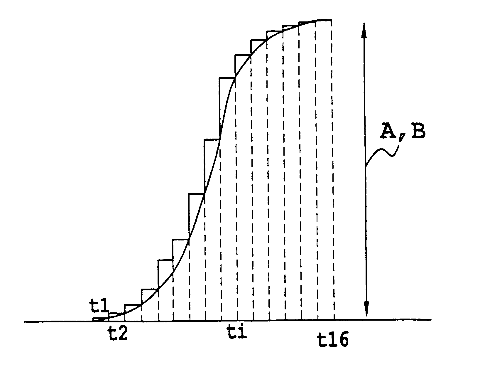
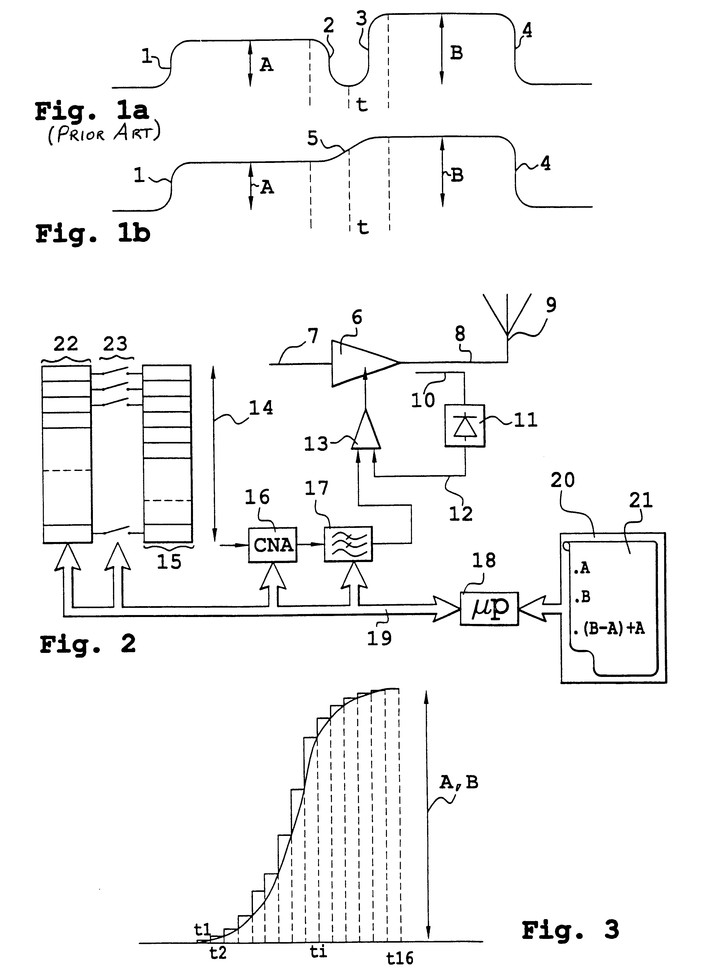
FIGS. 1a and 1b show, respectively for the prior art and for the invention, the nominal power differences that can be imposed in successive time slots if the same base station or the same mobile telephone requires to continue to transmit from one slot to the other. In FIGS. 1a (i.e. in the prior art), the nominal transmitted power is limited to "A" during a first time slot. This value results from communication between the base station and the mobile telephone. During this communication the base station sets a nominal power for the mobile telephone at which it must transmit for its message to be received correctly. Or vice versa. For the channel concerned, the base station and the mobile telephone are therefore restricted to an assigned power A. The assigned power can be different for the base station and for the mobile telephone. What is important is that there is an assigned power. The time slot with amplitude A begins with a rise in power 1 and ends with a fall in power 2. The ne...


PUM


Abstract

Problems of noise emission during transmission in successive time slots (A-B) in mobile telephony are solved by causing the transmitted power to change in a monotonic manner from a previous value to a new value. It is shown that this increases the transmission bit rate.

Description

The present invention concerns a method of transmitting in successive time slots within a transmission frame, in particular a Time-Division Multiple Access (TDMA) frame, in a radio communication system. The invention relates in particular to the field of time-division multiple access (as opposed to frequency-division multiple access (FDMA) or code-division multiple access (CDMA)) mobile telephony. Of course, it also concerns hybrid systems involving at least time-division multiple access. It is equally applicable to transmission by base stations and to transmission by mobile telephones. It is aimed principally at the field of high bit rate transmission.The time-division of different communication channels in successive time slots within a common frame is known in itself in the field of radio communications. A frame, for example a Global System for Mobile communications (GSM) frame, conventionally includes eight time slots (TS0 through TS7). A communication channel between a first mo...

Claims


Application Information

Patent Timeline
IPC IPC(8): H04B7/005H04J3/00H04B1/04
CPCH04W52/362H04W52/367
Inventor GENEST, PIERREPARISEL, ARNAUD
Owner ALCATEL LUCENT SAS
Why Eureka
Try Eureka