Flow measuring device based on predetermine class of liquid

a flow measurement and liquid technology, applied in the direction of liquid/fluent solid measurement, volume/mass flow by differential pressure, instruments, etc., can solve the problems of orifice restriction preventing the flow of liquid, low flow rate or flow rate of high viscosity liquid, etc., to achieve accurate measurement over a wide range of flow rate and liquid properties. , the accuracy of flow sensors

Inactive Publication Date: 2003-08-26
SYS
View PDF49 Cites 55 Cited by
  • Summary
  • Abstract
  • Description
  • Claims
  • Application Information

AI Technical Summary

Problems solved by technology

However, these particular types of flow sensors are generally not very accurate for measuring low flow rates or flow rates of high viscosity liquids.
The orifice restriction impedes the flow of liquid creating a pressure drop.
However, orifice flow sensors do not provide accurate measurements over a wide range of flow rates and liquid properties.
Additionally, the discharge coefficient is only accurate for a very specific flow meter configuration and application because it is dependent on the liquid being measured and the meter application properties.
Thus, a new discharge coefficient must be calculated if the liquid or application changes, rendering the discharge coefficient relatively useless in a system that must adjust to a variety of liquids with different physical properties.
Recursive calculations can be very time consuming and in some situation non-deterministic.
Thus, conventional discharge coefficients may not be very useful for correcting inaccurate flow rate measurements in systems in which the corrected flow rate calculations are done repeatedly at very short time intervals.

Method used


Image

  • Flow measuring device based on predetermine class of liquid
  • Flow measuring device based on predetermine class of liquid
  • Flow measuring device based on predetermine class of liquid

Examples


Embodiment Construction

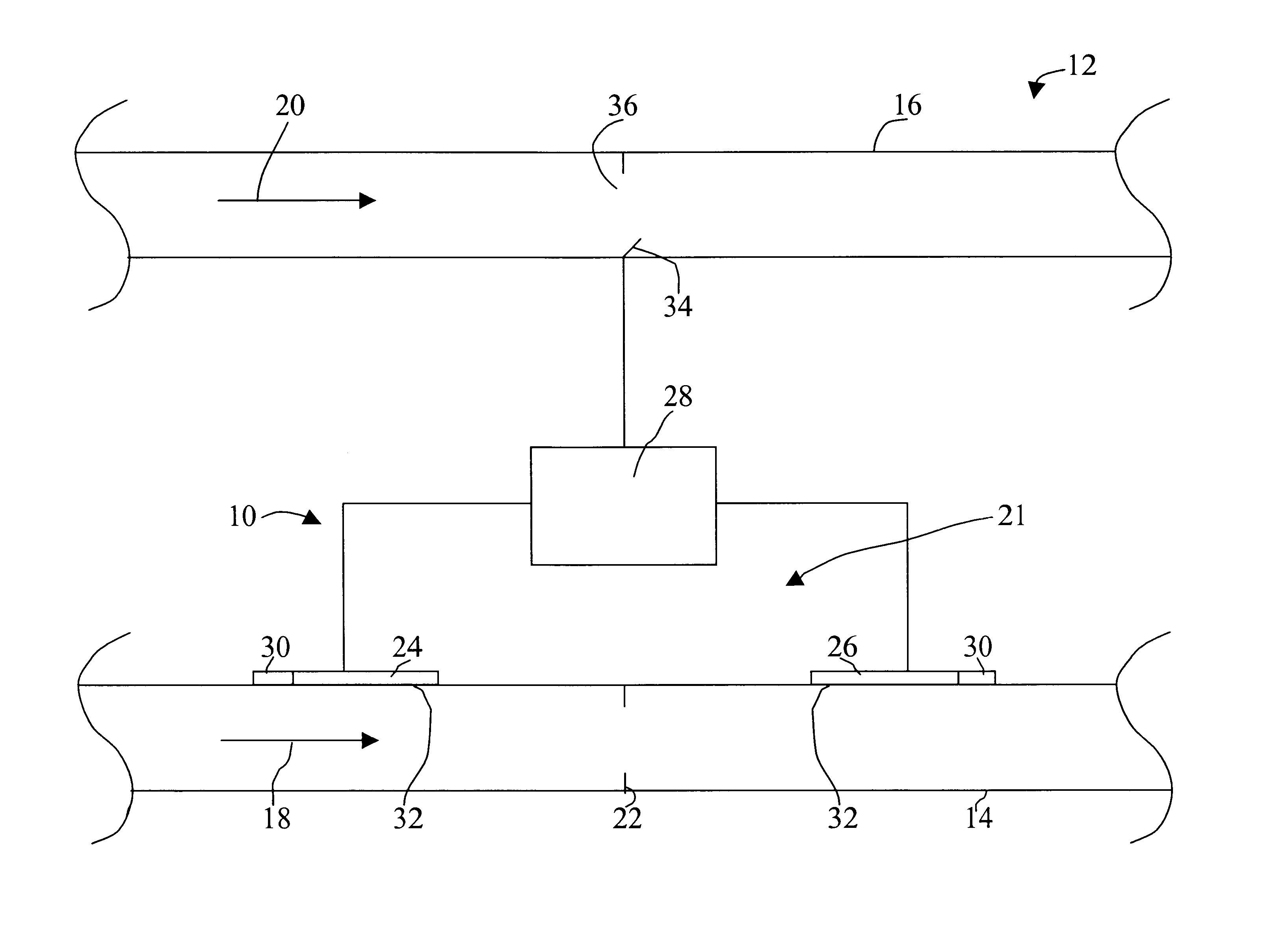
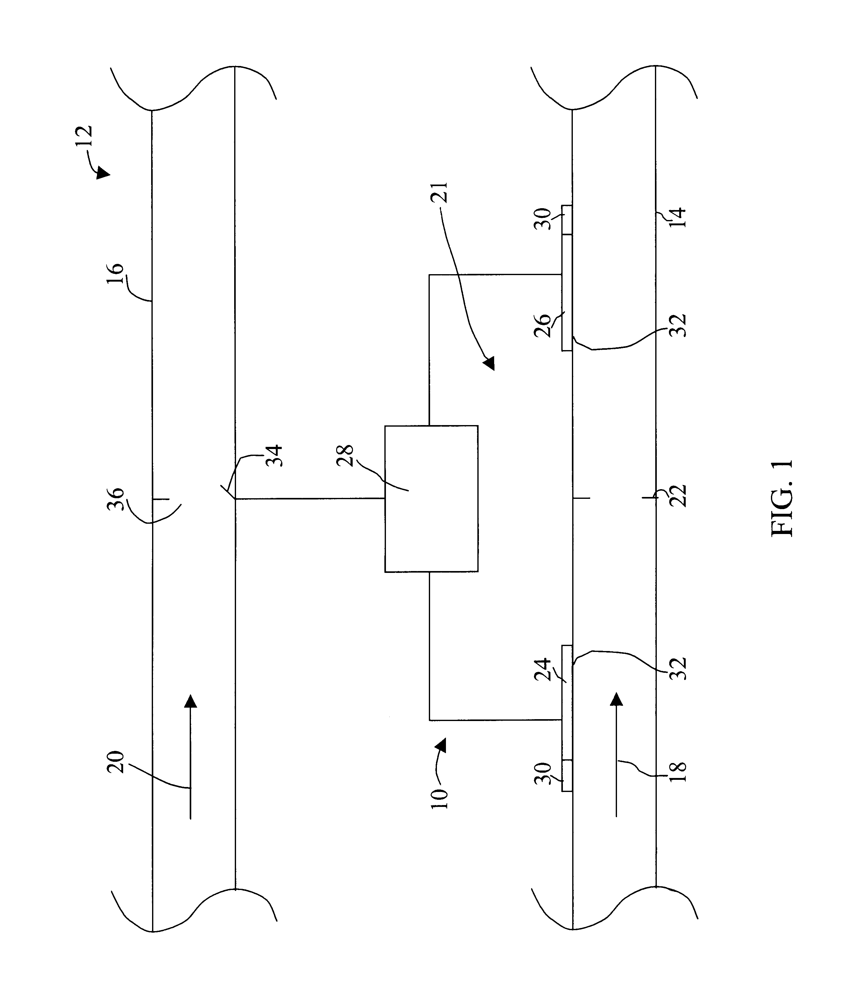
In accordance with the present invention, a flow meter is described that provides distinct advantages when compared to those of the prior art. The invention can best be understood with reference to the accompanying drawing figures.

Referring now to the drawings, a flow meter according to the present invention is generally designated by reference numeral 10 in FIG. 1. The flow meter 10 is shown, for purposes of illustrating its manner of operation, installed in a liquid beverage dispensing machine 12, details of the construction of which are not shown but are well known in the art. The liquid beverage dispensing machine 12 includes a first conduit 14 for dispensing liquid syrup and a second conduit 16 for dispensing water. The syrup flows freely through the first conduit 14 in the direction of arrow 18 and the water flows through the second conduit 16 in the direction of arrow 20, its flow rate being controlled by a valve 34. Preferably, the first and second conduits 14, 16 are circul...


PUM


Abstract

A flow meter and method for determining the corrected flow rate of a liquid falling into a predetermined class of liquids based on its viscosity and density is disclosed. The flow meter comprises a flow sensor for measuring an uncorrected flow rate of the liquid, a temperature sensor for measuring the temperature of the liquid, and a microprocessor for calculating the corrected flow rate based on the liquids predetermined class and the measured temperature. The flow sensor can include a restriction in the fluid flow path, first and second pressure sensors positioned one on each side of the restriction and a temperature sensor. The first and second pressure sensors measure the drop in fluid pressure created by the restriction and the temperature sensor measures the temperature of the liquid. By basing the corrected flow rate calculation on the predetermined class of the liquid, the calculation becomes a closed form solution that is deterministic providing for quick and accurate corrected flow rate calculation. A flow meter according to the present invention can be used in many applications such as, among others, liquid beverage dispensers and variable speed pumps.

Description

The present invention relates to flow meters for determining the flow rate of a liquid. More particularly, the present invention relates to flow meters capable of determining the corrected flow rate of a liquid based on a deterministic, closed solution.BACKGROUND INFORMATIONFlow sensors are generally used to measure an uncorrected flow rate of a liquid flowing in a confined space such as a conduit like a tube or pipe. Among the types of conventional flow sensors are paddle wheel sensors in which a rotatable paddle wheel is inserted into the flow path of a liquid. The flowing liquid causes the paddle wheel to rotate and the flow rate of the liquid is determined based on the speed of rotation of the paddle wheel. Another type of conventional flow sensor is a turbine flow sensor in shich the speed at which a turbine turns in a liquid is used to determine flow rate. However, these particular types of flow sensors are generally not very accurate for measuring low flow rates or flow rates...

Claims


Application Information

Patent Timeline
Patent Type & Authority Patents(United States)
IPC IPC(8): B67D1/00B67D1/08G01F1/34G01F1/684G01F1/36
CPCB67D1/0855B67D1/1211G01F1/36G01F1/6847
Inventor TIETSWORTH, STEVEN C.GOLDSTEIN, LAWRENCE H.O'NEIL, DONALD J.
Owner SYS
Why Eureka
Try Eureka