
Wall mountable assembly

a wall mount and assembly technology, applied in fishing, religious equipment, dwelling equipment, etc., can solve the problems of difficult replacement of exact matches, expensive and sometimes not truly effective, and difficult mounting of accessories, etc., and achieve the effect of convenient mounting

Inactive Publication Date: 2003-08-26
NYSTROM GROUP
View PDF13 Cites 38 Cited by
  • Summary
  • Abstract
  • Description
  • Claims
  • Application Information

AI Technical Summary

Benefits of technology

In its non-use configuration, the object support parts swings to a position which enables an easy mounting of base part to a supporting wall. After the base part has been fitted to the wall the object support part swings relative to the base part to its in use position. This causes the cam member to move between a loose and a tightened fitting with respect to the cover of the base part. The assembly further includes locking means to releasably lock with the cam member which blocks the cam member from moving away from the tightened fitting. This ensures that the object support part of the assembly stays in its use position.

Problems solved by technology

However, the mounting of the accessory is more difficult when working with a tiled wall surface.
If the homeowner wishes to remove the accessory from the tile the damage caused by the drilling typically necessitates replacement of the entire piece of tile.
This is costly and sometimes not truly effective because it can often be difficult to find an exact match as a replacement tile.
To date however, there is nothing available in the way of a suction cup mount, which will lock against premature release.
Furthermore, there is currently nothing available in the way of a suction cup mount, which presents an esthetically appealing appearance for use on high quality wall mounted accessories.

Method used


Image

  • Wall mountable assembly
  • Wall mountable assembly
  • Wall mountable assembly

Examples


Embodiment Construction

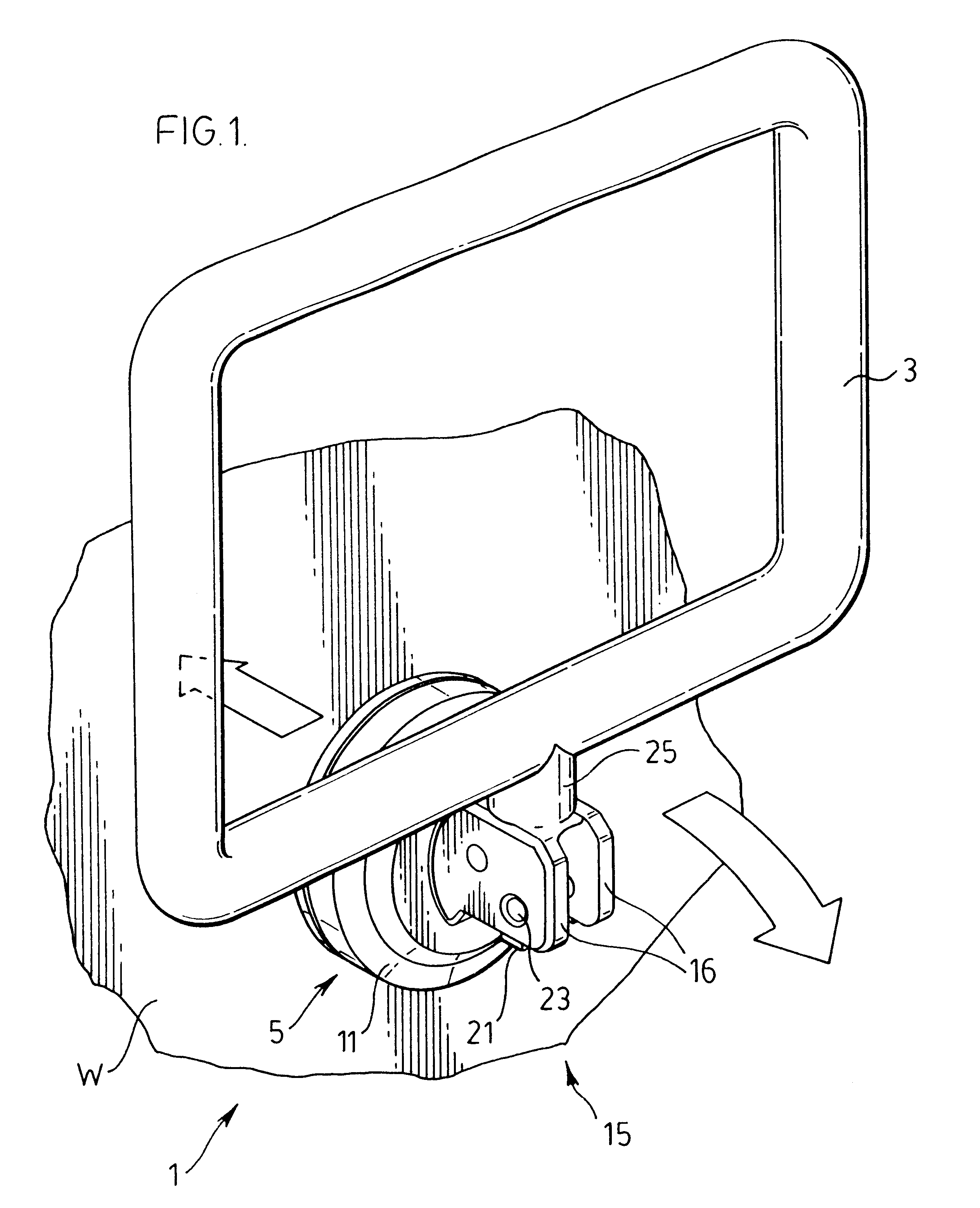
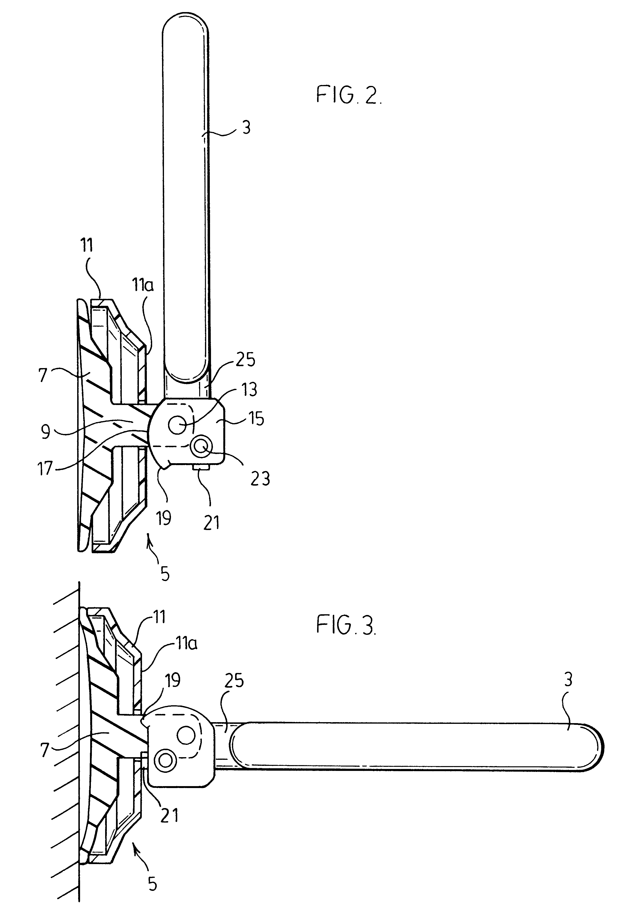
FIG. 1 shows a wall mountable assembly generally indicated at 1. This assembly includes an object support part in the form of a towel holder 3 and a base part generally indicated at 5.

FIGS. 1 and 2 show the towel holder 3 in a non-use position. FIGS. 3 and 4 show the towel holder after it has been swung to its use position.

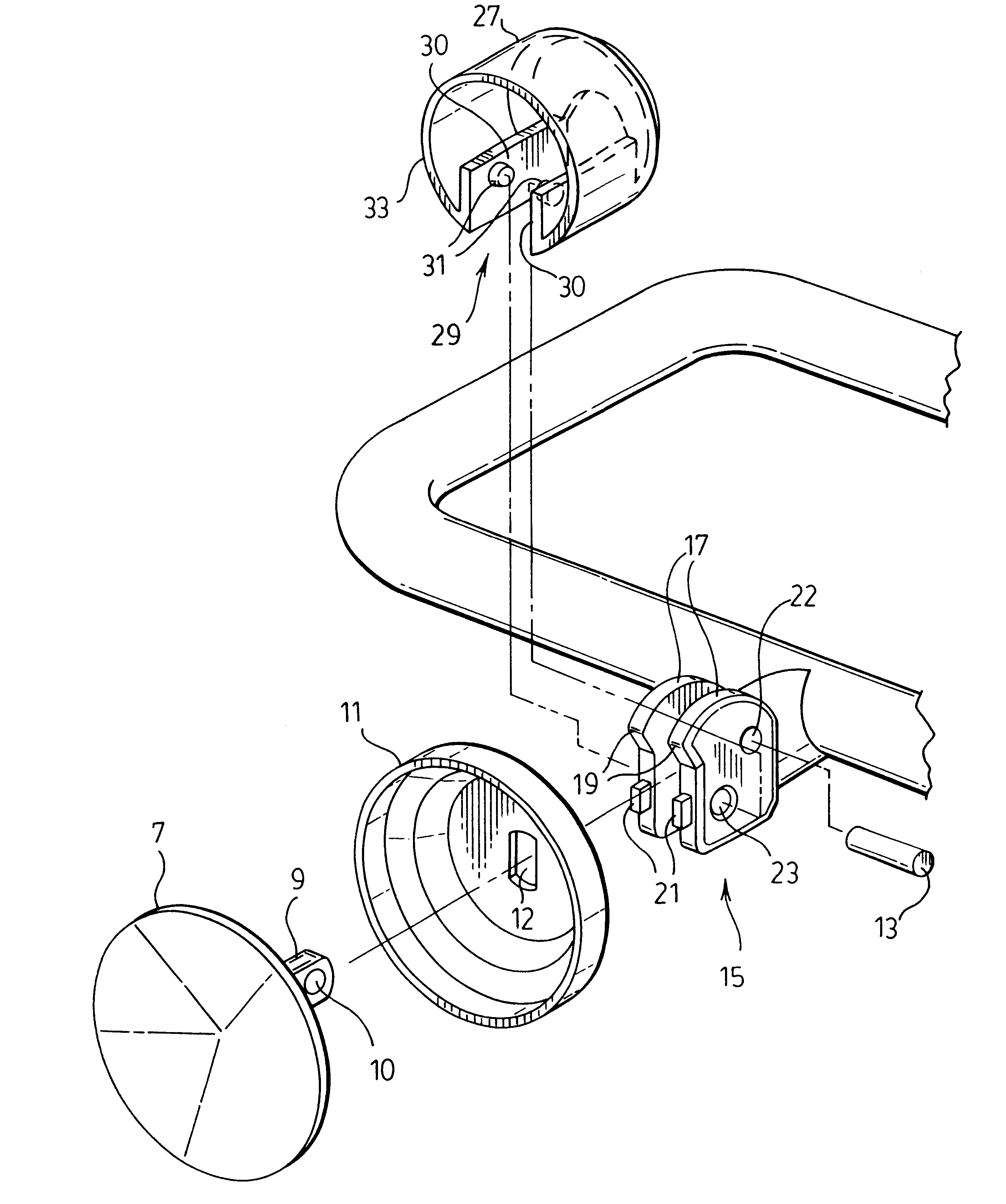
Referring now to FIGS. 5 and 6 the base part of the assembly comprises a wall attachment member 7 and a cover 11 which fits over the wall attachment member. In this particular case the wall attachment member is in the form of a suction cup.

The wall attachment member i.e., suction cup 7 is provided with a forwardly extending arm 9. This arm penetrates through an opening 12 centrally of cover 11.

The arm 9 includes a small opening 10 to receive a pin 13 as best seen in FIG. 6 of the drawings.

FIGS. 5 and 6 show that towel holder 3 includes a short base leg 25 fitted with a cam member 15. Cam member as seen for example in FIG. 1 of the drawings is formed by a pair of s...


PUM


Abstract

A wall mountable assembly such as a wall mountable towel ring or the like includes a base part and an object support part extending from the base part. The base part is formed from a wall attachment member and a cover member which fits over the wall attachment member. The wall attachment member has an arm which extends through the cover member and which secures by a pivot connection to a cam member at the inner end of the object support part of the assembly. The object support part is swingable from a non-use to a use position relative to the base part to cause the cam member to move between a loose and a tight fitting with respect to the cover of the base part. The assembly further includes a locking member which releasably secures to the cam member and which blocks the cam member from moving away from the tight fitting holding all of the components of the assembly tightly secured to one another.

Description

The present invention relates to a wall mountable assembly which includes an object support part extending from a base part that secures to a wall of a room. The object support part is preferably some type of a bathroom or kitchen accessory such as a towel bar, towel ring, soap dish etc.Wall mountable kitchen and bathroom accessories such as towel bars, towel rings, soap dishes, paper tissue holders, robe hooks etc. are used in essentially all homes. Typically these accessories have a one-piece rigid construction and are secured to a wall of a room by screws fitted through pre-set openings in the base of the accessory. This method of mounting is relatively simple when fitting the accessory to a wall having a wood or a plaster construction. However, the mounting of the accessory is more difficult when working with a tiled wall surface. The tiles must be drilled to receive the accessory. If the homeowner wishes to remove the accessory from the tile the damage caused by the drilling ty...

Claims


Application Information

Patent Timeline
IPC IPC(8): A47K10/00A47K10/04A47K10/12A47K5/00A47K5/04F16B47/00A45D42/00A45D42/14
CPCA47K5/04A47K10/04A47K10/12F16B47/006A45D42/14A47K2201/00
Inventor KNAPP, DAVID
Owner NYSTROM GROUP
Features
  • Generate Ideas
  • Intellectual Property
  • Life Sciences
  • Materials
  • Tech Scout
  • Unparalleled Data Quality
  • Higher Quality Content
  • 60% Fewer Hallucinations
Learn More