Method and apparatus for coding moving picture

a technology of moving picture and coding method, which is applied in the field of moving picture coding method and apparatus, can solve the problems of frame delay between input of picture signal and coding, deterioration of picture quality, and increase of m value (distance between each "i- and p-pictures" and "p-p pictures")

Inactive Publication Date: 2003-08-26
NEC CORP
View PDF12 Cites 63 Cited by
  • Summary
  • Abstract
  • Description
  • Claims
  • Application Information

AI Technical Summary

Problems solved by technology

As a result, quantization errors caused by coding are accumulated and become conspicuous and it causes deterioration in picture quality.
Although the bidirectional prediction has such an advantage, increase in the M value (distance between each "I- and P-pictures" and "P-P pictures") is disadvantageous for the interframe predictive coding.
Consequently, there is a frame delay between input of a picture signal and coding.
A disadvantage of the first related art is that the M value cannot be always optimized merely by using the distribution of detected motion vectors since the predictability does not simply depend on ...

Method used


Image

  • Method and apparatus for coding moving picture
  • Method and apparatus for coding moving picture
  • Method and apparatus for coding moving picture

Examples


first embodiment

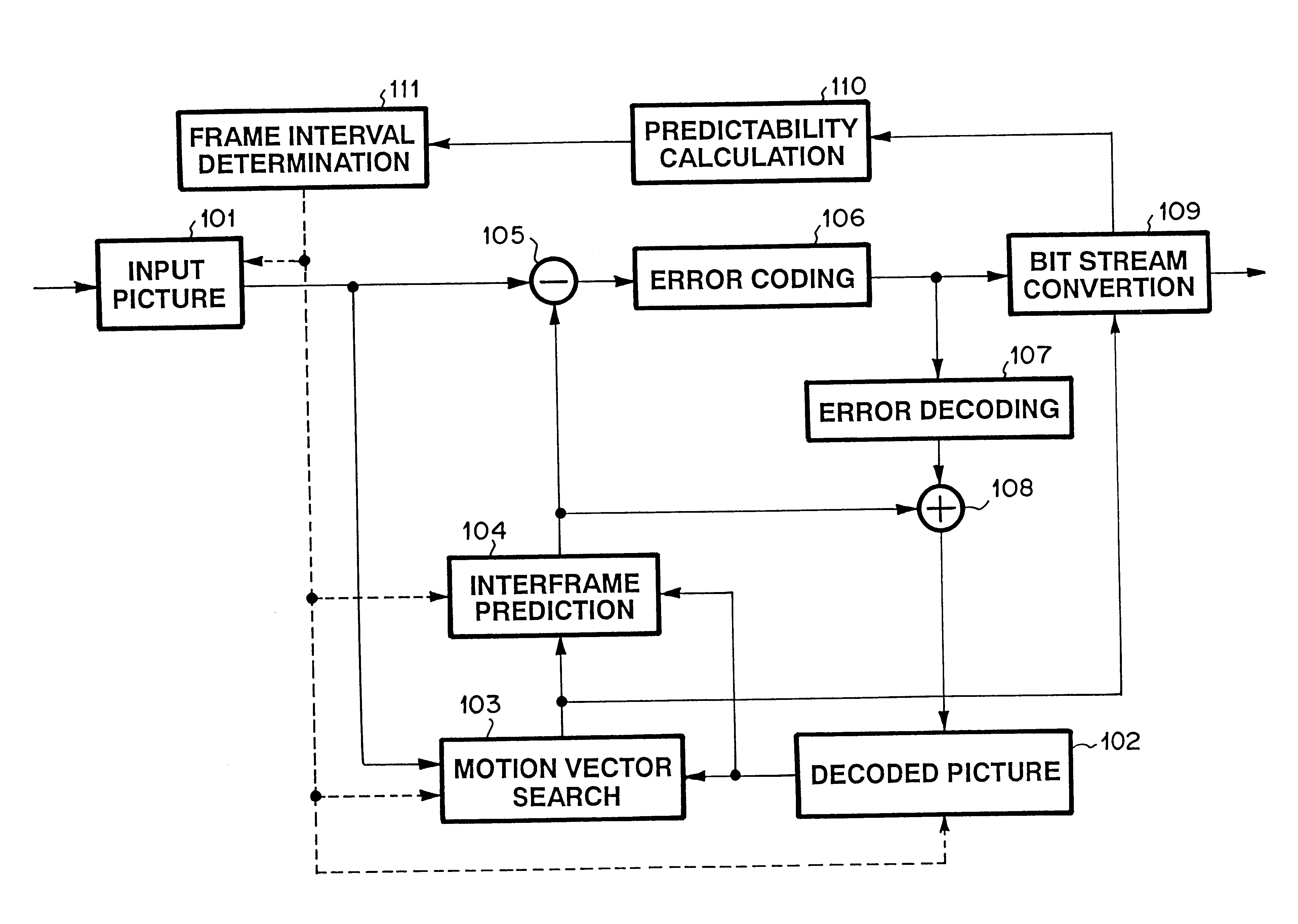
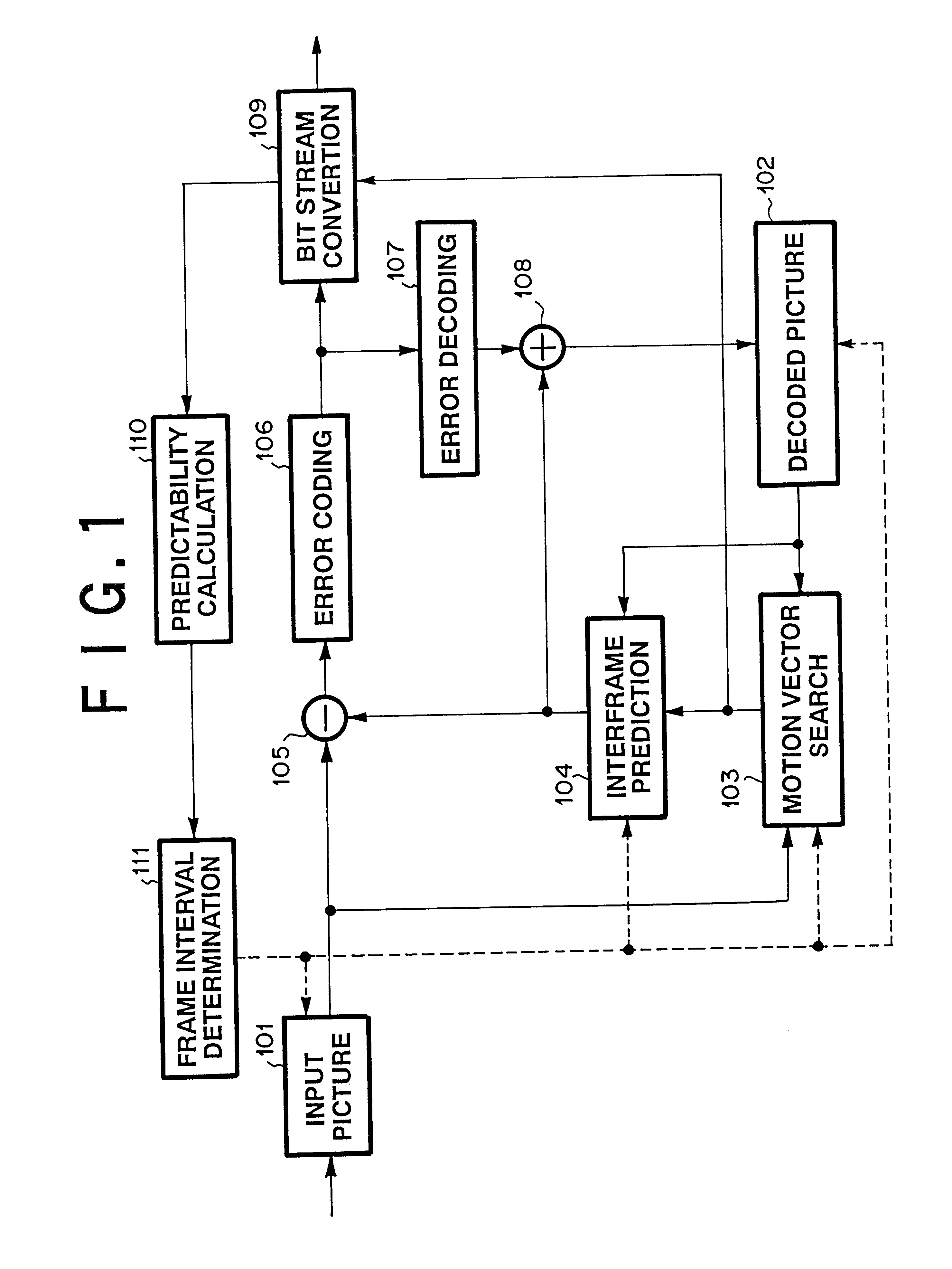
FIG. 1 is a diagram showing the invention. In FIG. 1, a moving picture coding apparatus of the invention comprises an input picture storage unit 101, a local-decoded picture storage unit 102, a motion vector searching unit 103, a motion compensation interframe predicting unit 104, a subtractor 105, a prediction error coding unit 106, a prediction error decoding unit 107, an adder 108, a bit stream converting unit 109, a predictability calculating unit 110, and a prediction frame interval determining unit 111.

The input picture storage unit 101 stores at least input pictures of the number which can be coded with a necessary frame delay and outputs the stored input picture signals in the coding order in accordance with a predicted structure determined by the prediction frame interval determining unit 111. After that, an input picture is preliminarily divided into a plurality of areas and each of the divided areas is subjected to a coding process.

The local-decoded picture storage unit 1...

second embodiment

A case of switching the M value between 3 and 1 will be described here. FIG. 5 is a flowchart for explaining the operations in the invention and shows the procedure of coding a picture.

First, in Step 501, a picture in each frame is coded according to the prediction frame interval and the coding picture type determined by the prediction frame interval determining unit 133.

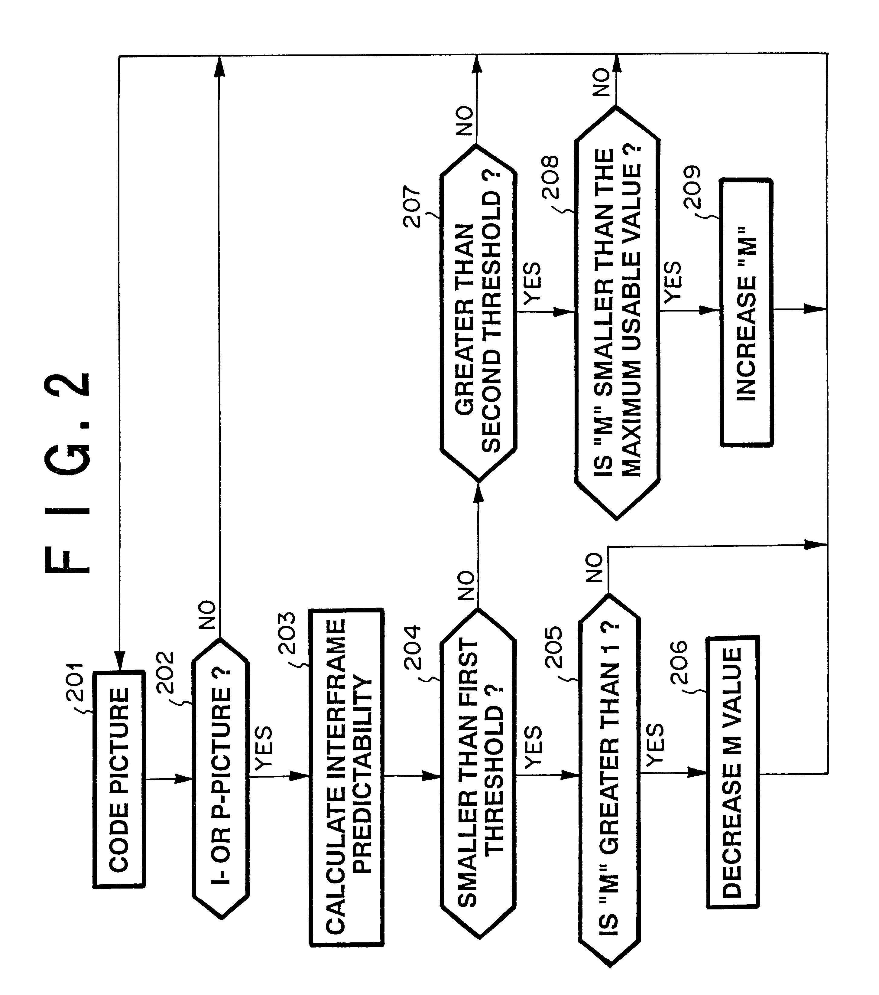
After completion of the process of coding the picture, in Step 502, the picture type is determined. When the picture is neither an I-picture (I frame) nor a P-picture (P frame), the routine directly advances to the following picture coding process. When the picture is either an I-picture (I frame) or a P-picture (P frame), the predictability of the picture is calculated in Step 503.

Subsequently, processes in Steps 504, 506, 507 and 509 are executed. When the M value is 3 and the calculated interframe predictability is smaller than a first threshold, the M value is decreased to 1. If NO, the M value is maintained and...


PUM


Abstract

A moving picture coding apparatus and method with improved predictability of a moving picture to be subjected to interframe prediction to obtain an improved quality of a coded picture. In a moving picture coding apparatus for performing interframe motion compensated prediction for applying intraframe coding, interframe forward predictive coding and interframe bidirectional predictive coding to code each frame, by determining a prediction frame interval of frames to be subjected to forward prediction on the basis of interframe predictability, a moving picture is coded while the coder is adaptively changing the prediction frame interval in accordance with the predictability.

Description

1. Technical field of the InventionThe present invention relates to an apparatus which realizes picture coding, for example, moving picture coding defined by a standard such as ISO / IEC 13818-2 (MPEG-2) and, more particularly, to a high picture quality coding control system.2. Description of the Prior ArtHitherto, in the case of performing motion compensated interframe predictive coding defined by a standard such as ISO / IEC 13818-2 (MPEG-2), generally, the three kinds of picture types of an intraframe coded picture (I-picture (I frame)), an interframe forward predictive coded picture (P-picture (P frame)), and an interframe bidirectionally predictive-coded picture (B-picture (B frame)) are arranged in an ordered pattern which is generally fixed.It is common in the technical field to which the present invention belongs that the distance between the I-pictures (I frames) is expressed by "N" and the distance between the I-picture and the P- picture (P-frame) or between the P-pictures is...

Claims


Application Information

Patent Timeline
IPC IPC(8): G06T9/00H04N7/50H04N7/46H04N7/26H04N19/107H04N19/114H04N19/50H04N19/132H04N19/136H04N19/137H04N19/14H04N19/142H04N19/172H04N19/196H04N19/503H04N19/593H04N19/85
CPCH04N19/105H04N19/159H04N19/149H04N19/15H04N19/61H04N19/114H04N19/152H04N19/156H04N19/577
Inventor YOKOYAMA, YUTAKA
Owner NEC CORP
Why Eureka
Try Eureka