Optical configuration for improved lens performance

a technology of optical configuration and lens, applied in the field of optical imaging, can solve the problem of only correcting the curvature of the field, and achieve the effects of improving bulk and cost, simple lens system, and low cos

Inactive Publication Date: 2003-09-02
LEIDOS
View PDF8 Cites 8 Cited by
  • Summary
  • Abstract
  • Description
  • Claims
  • Application Information

AI Technical Summary

Benefits of technology

The present invention provides a method for imaging light from a set of integrated optical light guides arranged over an extended field of view with a simple, inexpensive lens system. The invention contributes to high performance in the form of a reliable, robust, manufacturable, low-cost component for optical devices used for optical data storage, bar code readers, image scanning for digitization or xerography, laser beam printers, inspection systems, densitometers, and 3-dimensional scanning (surface definition, surface characterization, robotic vision).
Integrated optics can be used to direct multiple light sources through parallel light guides toward the same focusing lens, which images the light guide exit apertures onto separate spots. Re-imaging returns the light reflected from each spot to the light guide from which it originated, where it can be separately detected. With integrated optics, the number of parallel light guides acting as sources can be increased as necessary. However, the light guides must occupy different positions in the field of view of the lens. Using integrated optics fabrication methods, it is easiest to arrange them in a straight line so that the light guides can be fabricated in a single flat sheet of material and terminate with their exit apertures along one edge facing the lens. If the light guides are spaced at a constant distance from each other, every time a light guide is added to increase the number of sources, it occupies a position in the lens field of view that is further away from the lens axis. For a simple lens system, the number of light guides that can be satisfactorily imaged is limited to those within the field of view set by curvature of field effects. In addition, as sources are positioned further from the optical axis of the lens system, their light may be partially cut off by the limiting aperture of the lens system (an effect called vignetting) if the axis of the emitted cone of light is still parallel to the optical axis. Lens systems can be designed that accept light cones parallel to the optical axis without vignetting; such systems may be oversize, telecentric, or both, resulting in increased bulk and cost. A single lens requires light cones that are directed at the center of the lens, so that the entire lens is illuminated for best light efficiency and smallest focal spot size. A simple lens system may require light cones directed either toward or away from the optical axis, depending on system details; the light must be centered on the limiting aperture of the system, which may not be the first lens encountered.
The present invention extends the performance of a simple lens system with curvature of field to image a set of optical light guide sources extended over a wide field of view. The invention is applicable to systems using integrated optical light guides as the sources for imaging. It can allow such systems to use a wide field of view with simple aspheric lenses with resulting savings in complexity, size, mass, and cost.

Problems solved by technology

Further, while most aberrations in inexpensive lenses can be corrected using modem molding technology to reproduce aspheric or binary-diffraction lens surfaces, curvature of field is only correctable with costly lens designs involving many elements.

Method used


Image

  • Optical configuration for improved lens performance
  • Optical configuration for improved lens performance
  • Optical configuration for improved lens performance

Examples


Embodiment Construction

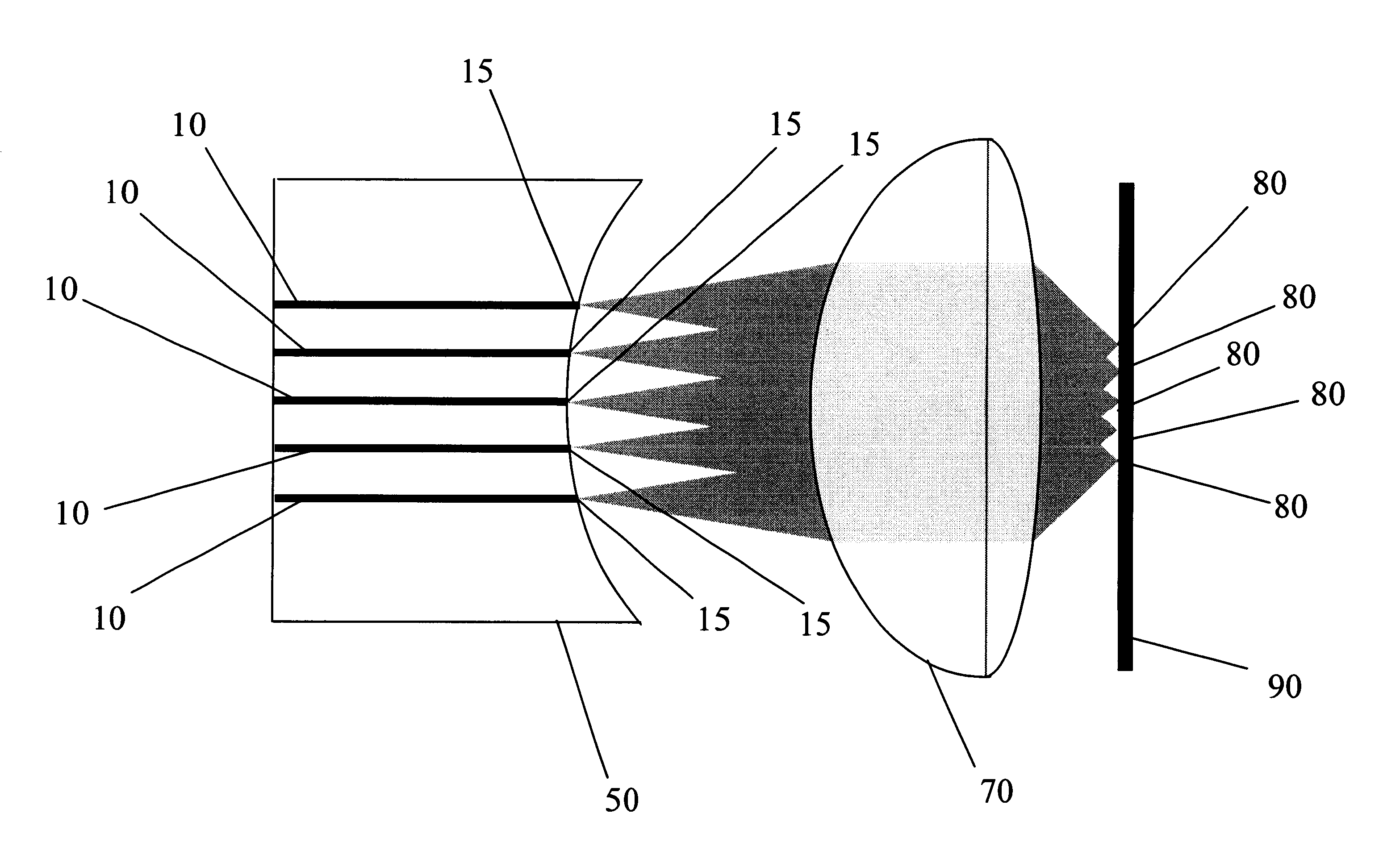
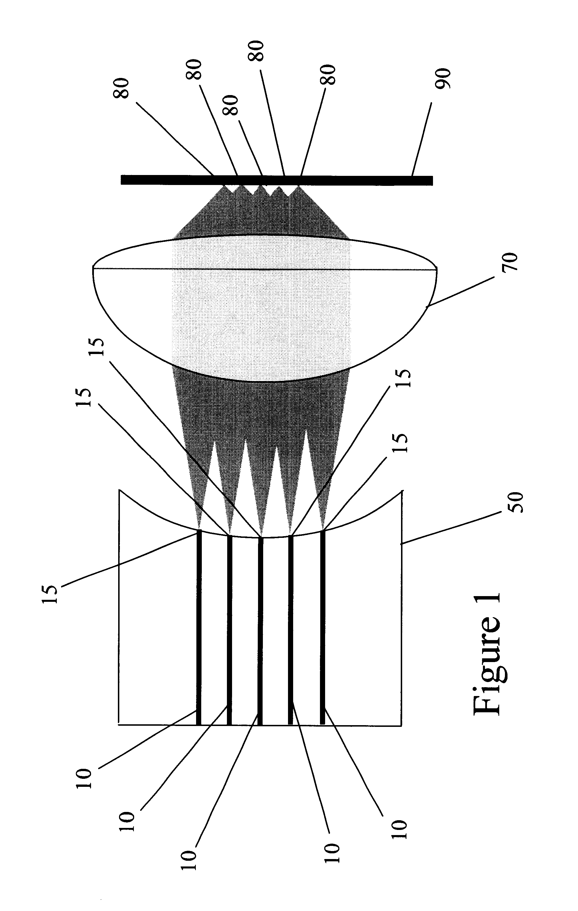
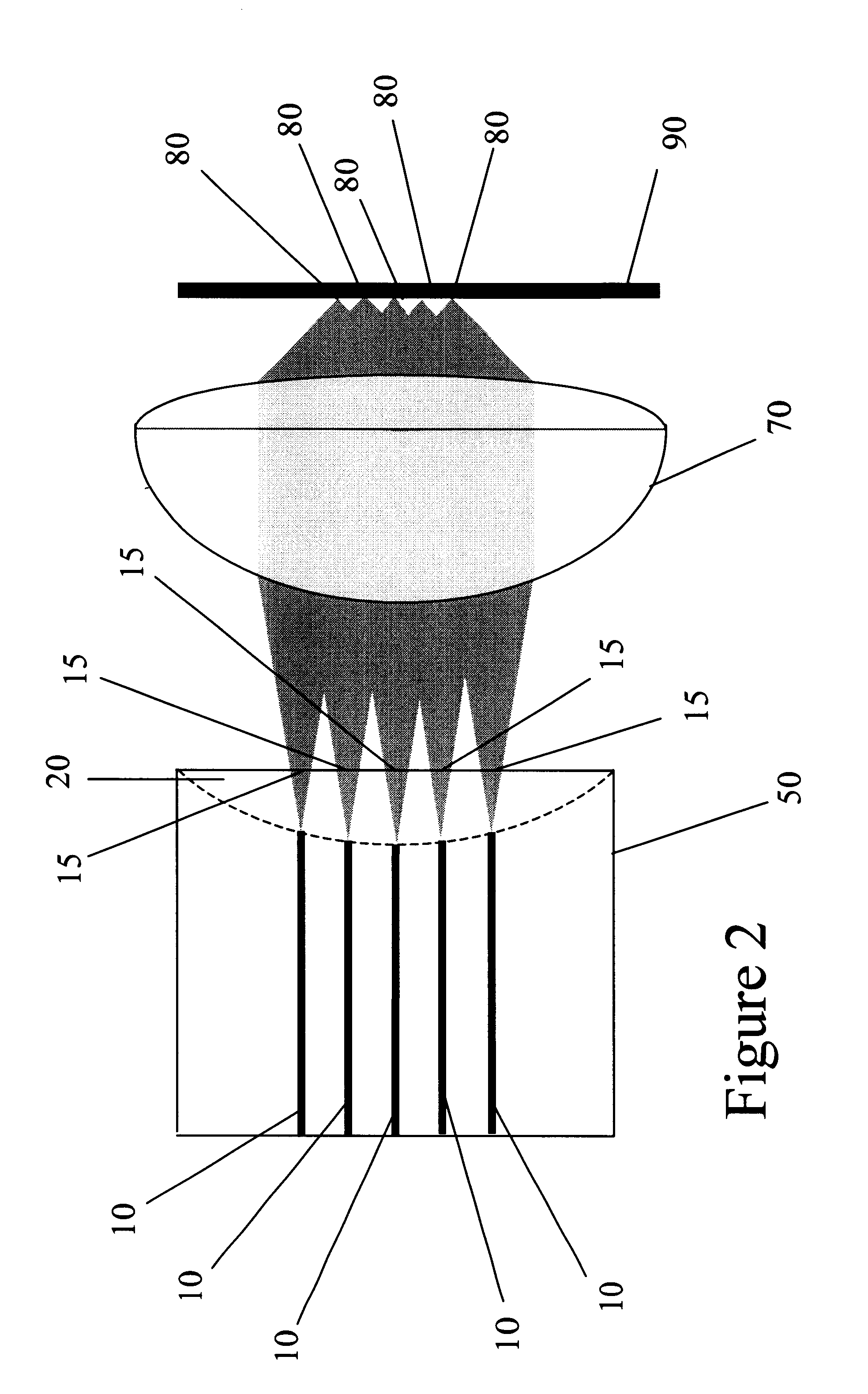
As sources are imaged further and further from the optical axis of a lens system (i.e., the central axis of the lens), the performance of the lens starts to fall off. The present invention allows diffraction-limited imaging of the waveguide exit apertures by a simple lens system for waveguides positioned well off the optical axis where curvature of field of the lens is significant.

The present invention applies to an integrated optics system or an optical fiber system. While the following discussion, embodiments and figures use an integrated optics chip as an example, it is contemplated in at least one embodiment of the present invention that fiber optics may be used. Further, one skilled in the art recognizes the various multiple source, light guide systems that may be used as a component in the optical systems described herein. An integrated optics chip (e.g., an integrated photonics chip) is an optical circuit manufactured using the same processes that are used to manufacture inte...


PUM

PropertyMeasurementUnit
optical energyaaaaaaaaaa
opticalaaaaaaaaaa
areaaaaaaaaaaa

Abstract

Described herein is a system and method for extending the performance of a simple lens system with curvature of field to image a set of optical light guide sources extended over a wide field of view. Embodiments are applicable to systems using integrated optical light guides as the sources for imaging. Further, the systems and methods allow for a wide field of view using simple aspheric lenses with resulting savings in complexity, size, mass, and cost.

Description

1. Field of the InventionThis invention relates generally to the field of optical imaging. More particularly, the invention relates to the field of imaging through improved beam source and lens configurations.2. Description of the Related ArtMany optical devices involve collecting light from a source (such as a laser) and manipulating it with a lens system. The lens system may be used to project the light as a collimated beam or to focus the light to a concentrated spot. For example, optical scanning of a surface is generally done with a focused spot to provide localized interaction with a small area of the surface at any one time. Optical scanners have been developed for a variety of uses including optical data storage, bar code readers, image scanning for digitization or xerography, laser beam printers, inspection systems, densitometers, and 3-dimensional scanning (surface definition, surface characterization, robotic vision). In these scanning applications, the light spot is scan...

Claims


Application Information

Patent Timeline
Patent Type & Authority Patents(United States)
IPC IPC(8): G02B6/32G02B6/26G11B7/09G11B7/135G11B7/12G02B6/36G02B6/00G02B6/42G11B7/14
CPCG02B6/26G02B6/32G11B7/0908G11B7/1206G11B7/1374G11B7/1384G11B7/14G02B6/42G02B6/4224G02B6/425G02B2006/0098G11B2007/13727G11B7/124
Inventor WYETH, NEWELL CONVERSPHILLIPS, EDWARD ALAN
Owner LEIDOS
Why Eureka
Try Eureka