Piston control mechanism of reciprocating internal combustion engine of variable compression ratio type

a technology of variable compression ratio and control mechanism, which is applied in the direction of positive displacement engines, bearings, shafts and bearings, etc., can solve the problems of unsatisfactory interference between piston 104 and intake and exhaust valves, and achieve the effects of narrowing the range, compact size, and sacrificing engine performan

Inactive Publication Date: 2003-09-09
NISSAN MOTOR CO LTD
View PDF11 Cites 19 Cited by
  • Summary
  • Abstract
  • Description
  • Claims
  • Application Information

AI Technical Summary

Benefits of technology

Accordingly, an object of the present invention is to provide a piston control mechanism of reciprocating internal combustion engine, which is free of the above-mentioned undesired piston displacement.
Another object of the present invention is to provide a piston control mechanism of reciprocating internal combustion engine of variable compression ratio type, which can assuredly avoid interference between a piston and intake and exhaust valves without sacrificing engine performance, that is, without narrowing a range in which the engine compression ratio is variable.
Still another object of the present invention is to provide a piston control mechanism of reciprocating internal combustion engine of variable compression ratio type, which is compact in size and exhibits a high cost performance.

Problems solved by technology

Furthermore, if the displacement of piston 104 becomes remarkably large, undesirable interference between piston 104 and intake and exhaust valves may occur.

Method used


Image

  • Piston control mechanism of reciprocating internal combustion engine of variable compression ratio type
  • Piston control mechanism of reciprocating internal combustion engine of variable compression ratio type
  • Piston control mechanism of reciprocating internal combustion engine of variable compression ratio type

Examples


first embodiment

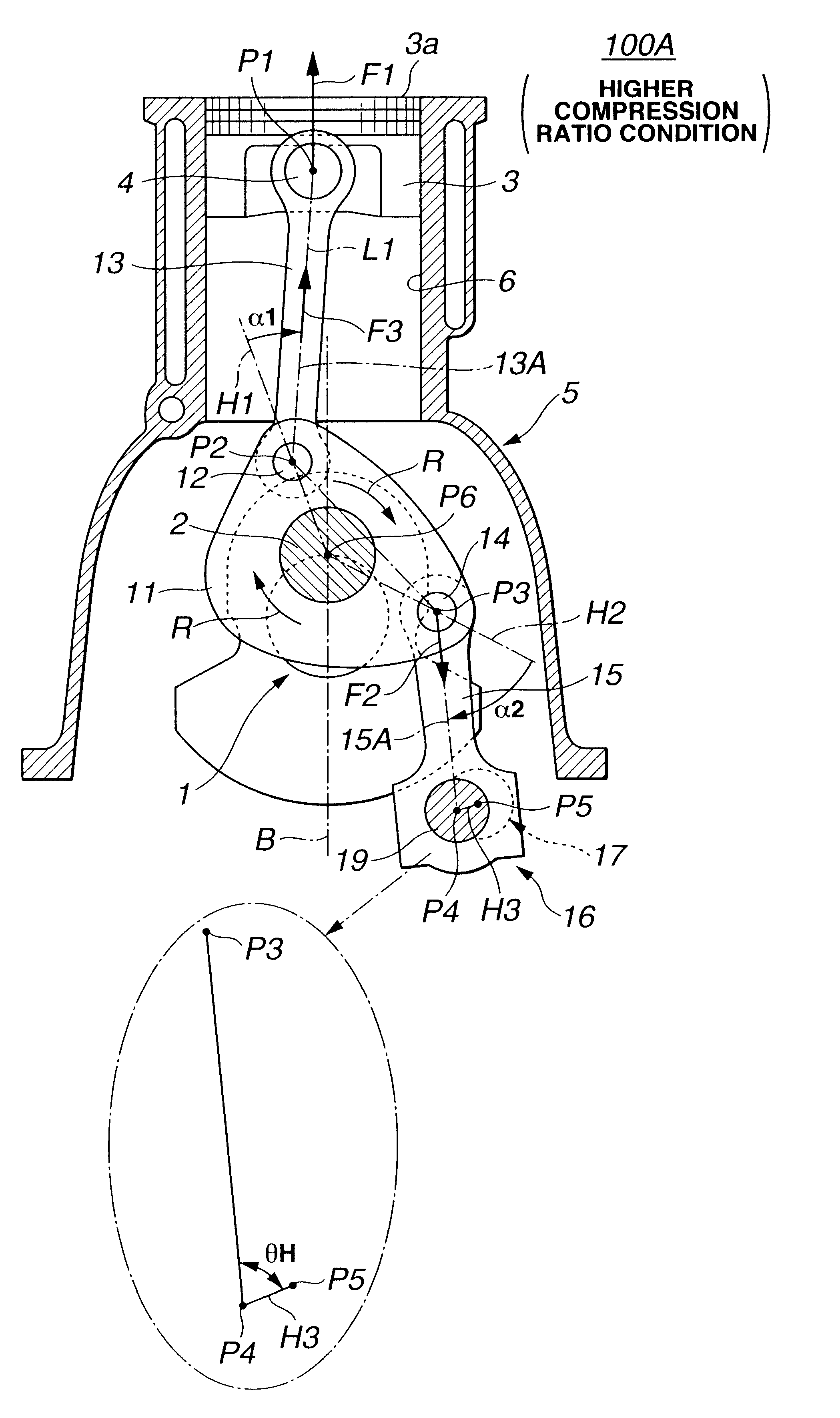
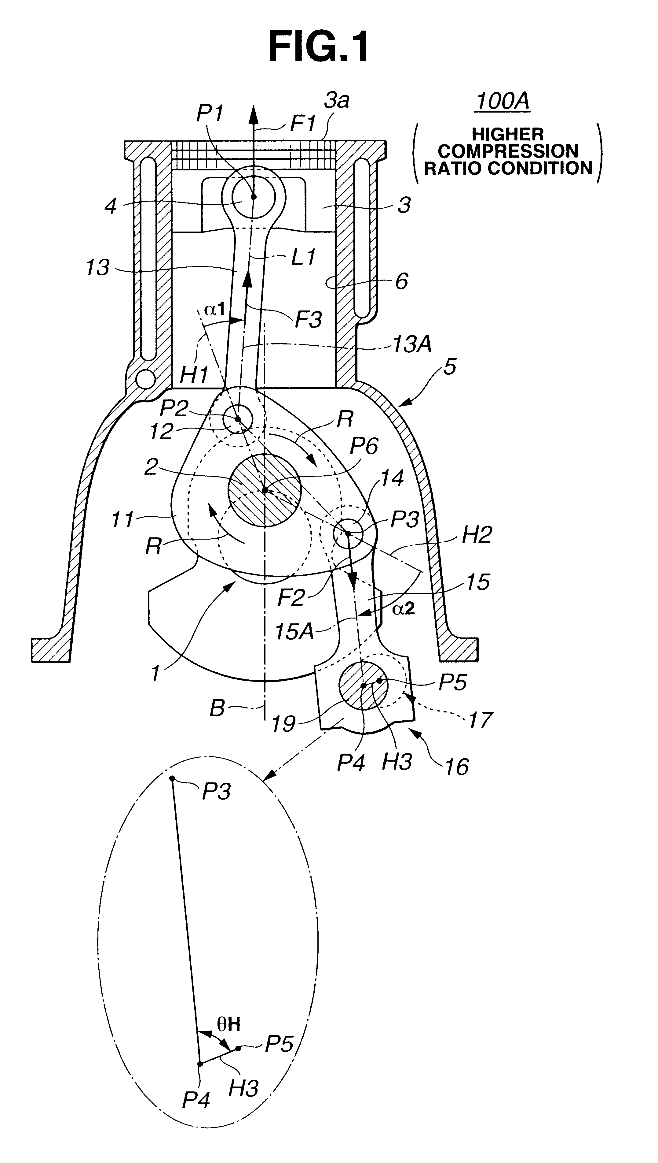
Referring to FIGS. 1 to 9A and 9B, particularly FIGS. 1 and 2, there is shown a piston control mechanism of the present invention, which is applied to a reciprocating internal combustion engine of variable compression ratio type.

As is seen from FIG. 1, the piston control mechanism 100A of the first embodiment comprises a lower link 11 which is rotatably disposed on a crank pin 2 of a crankshaft 1 of an associated internal combustion engine at a center opening thereof. A center axis of crank pin 2 is denoted by reference P6. The lower link 11 is shaped generally triangle. An upper link 13 is pivotally connected at a lower end to lower link 11 through a first connecting pin 12 and pivotally connected at an upper end to a piston 3 through a piston pin 4. A center axis of first connecting pin 12 is denoted by reference P2 and a center axis of piston pin 4 is denoted by reference P1. A control link 15 is pivotally connected at an upper end to lower link 11 through a second connecting pin...

second embodiment

Referring to FIG. 10, there is shown a piston control mechanism 100B of the present invention.

In this embodiment 100B, when piston 3 is at the top dead center (TDC), center axis P2 of first connecting pin 12 and center axis P3 of second connecting pin 14 are positioned at the same side with respect to the imaginary plane B that includes center axis P6 of crank pin 2 of crankshaft 1 and is parallel with the axis of cylinder 6 of the engine, and supporting axis P4 of control link 15 is positioned above center axis P3 of second connecting pin 14. That is, control link 15 extends diagonally upward from lower link 11, which causes positioning of control crankshaft 17 above crankshaft 1. Thus, as compared with the above-mentioned first embodiment 100A, the second embodiment 100B is somewhat poor in layout.

However, also in the second embodiment 100B, when piston 3 is at the top dead center (TDC), a rotation direction P1 of upper link center line 13A relative to first direction line H1 is e...

third embodiment

Referring to FIG. 11, there is shown a piston control mechanism 100C of the present invention.

In this third embodiment 100C, when, under a higher compression ratio condition, piston 3 comes up to the top dead center on exhaust stroke, the eccentric angle .theta.H defined between third direction line H3 (see FIG. 8B) and control link center line 15A is set 0 (zero) degree. Accordingly, in this third embodiment 100C, under the condition wherein piston crown 3a comes to a position closes to the intake and exhaust valves, the bending deformation of control crankshaft 17 is most effectively suppressed and thus the possibility of contact of piston crown 3a with the intake and exhaust valves is assuredly suppressed.

The entire contents of Japanese Patent Application 2001-091742 filed Mar. 28, 2001 are incorporated herein by reference.

Although the invention has been described above with reference to the embodiments of the invention, the invention is not limited to such embodiments as describ...


PUM


Abstract

In an internal combustion engine of variable compression ratio type, a piston control mechanism is employed which comprises a lower link rotatably disposed on a crank pin of a crankshaft of the engine, an upper link having one end pivotally connected to the lower link and the other end pivotally connected to a piston of the engine, a control link having one end pivotally connected to the lower link; and a position changing mechanism which changes a supporting axis about which the other end of the control link turns. When the piston comes up to a top dead center, a compression load is applied to the control link in an axial direction of the control link in accordance with an upward inertial load of the piston.

Description

BACKGROUND OF INVENTION1. Field of InventionThe present invention relates in general to reciprocating internal combustion engines of a variable compression ratio type that is capable of varying a compression ratio under operation thereof and more particularly to the reciprocating internal combustion engines of a multi-link type wherein each piston is connected to a crankshaft through a plurality of links. More specifically, the present invention is concerned with a piston control mechanism of such internal combustion engines.2. Description of Related ArtIn the field of reciprocating internal combustion engines, there has been proposed a variable compression ratio type that is capable of varying a compression ratio of the engine in accordance with operation condition of the same. One of such engines is shown in Laid-Open Japanese Patent Application (Tokkai) 2000-73804. The engine of the publication employs a piston control mechanism wherein each piston is connected to a crankshaft th...

Claims


Application Information

Patent Timeline
Patent Type & Authority Patents(United States)
IPC IPC(8): F02B75/00F02B75/04F01B9/02F01B31/14F02D15/02F16C7/00
CPCF02B75/045F02B75/048
Inventor MOTEKI, KATSUYAAOYAMA, SHUNICHIUSHIJIMA, KENSHIHIYOSHI, RYOSUKE
Owner NISSAN MOTOR CO LTD
Why Eureka
Try Eureka