Fastening means

a technology of fastening means and rods, which is applied in the direction of rod connections, couplings, manufacturing tools, etc., can solve the problems of operator or user fatigue, affecting the operation of the operator, and the rod is unstably held within the collar, so as to prevent loose working, minimize the operating time of securing the base, and operate with a very small force

Inactive Publication Date: 2003-09-16
WANG SHYH JEN +3
View PDF6 Cites 11 Cited by
  • Summary
  • Abstract
  • Description
  • Claims
  • Application Information

AI Technical Summary

Benefits of technology

It is an object of the present invention to provide an apparatus and method for fastening a base on a rod or column securely. It is also an object of the present invention to provide a fastening means capable of securing a base on a rod or column that is greater than that which is provided either by using a conventional bolt-pressing or a conventional bolt-clamping fastening device. Another object of the present invention is to provide a fastening means having wedge-shape contact serving as a toggle-like-mechanism which is capable of being operated with very small force. Also another object of the present invention is to provide a fastening means capable of minimizing operating time of securing a base on a rod or column provided by interference between them.
Still another object of the present invention is to provide a fastening means capable of securing parts by set screws as a whole modulus to prevent working loose.
The present invention is a fastening means including a holding base capable of sliding or rotating on a rod or column, a driving bolt rotatably coupled with a thrusting block with a driving wedge face rotatably engaged in the holding base, and a follower block movably reciprocating in the holding base and having a wedge face tangentially engageable with the driving wedge face of the thrusting block; whereby upon a rotation of the driving bolt to push the thrusting block in the holding base, the follower block will be thrusted by the driving block to interfere in a rod (or column) surface for quickly, ergonomically and firmly fastening the rod (or column) on the holding base.

Problems solved by technology

However, such a conventional fastening device has the following drawbacks: 1. The screw portion S has a single-point compressing on the rod R, easily causing loosening or rotation of the rod unstably held within the collar.
Great force is required for firmly fastening the collar on the rod, easily causing tiredness to the operator or user.
Even the contact surface between the rod and the clamp is increased, it still requires a large force for firmly fastening the rod, causing difficulty for the user.

Method used


Image

  • Fastening means
  • Fastening means
  • Fastening means

Examples


Embodiment Construction

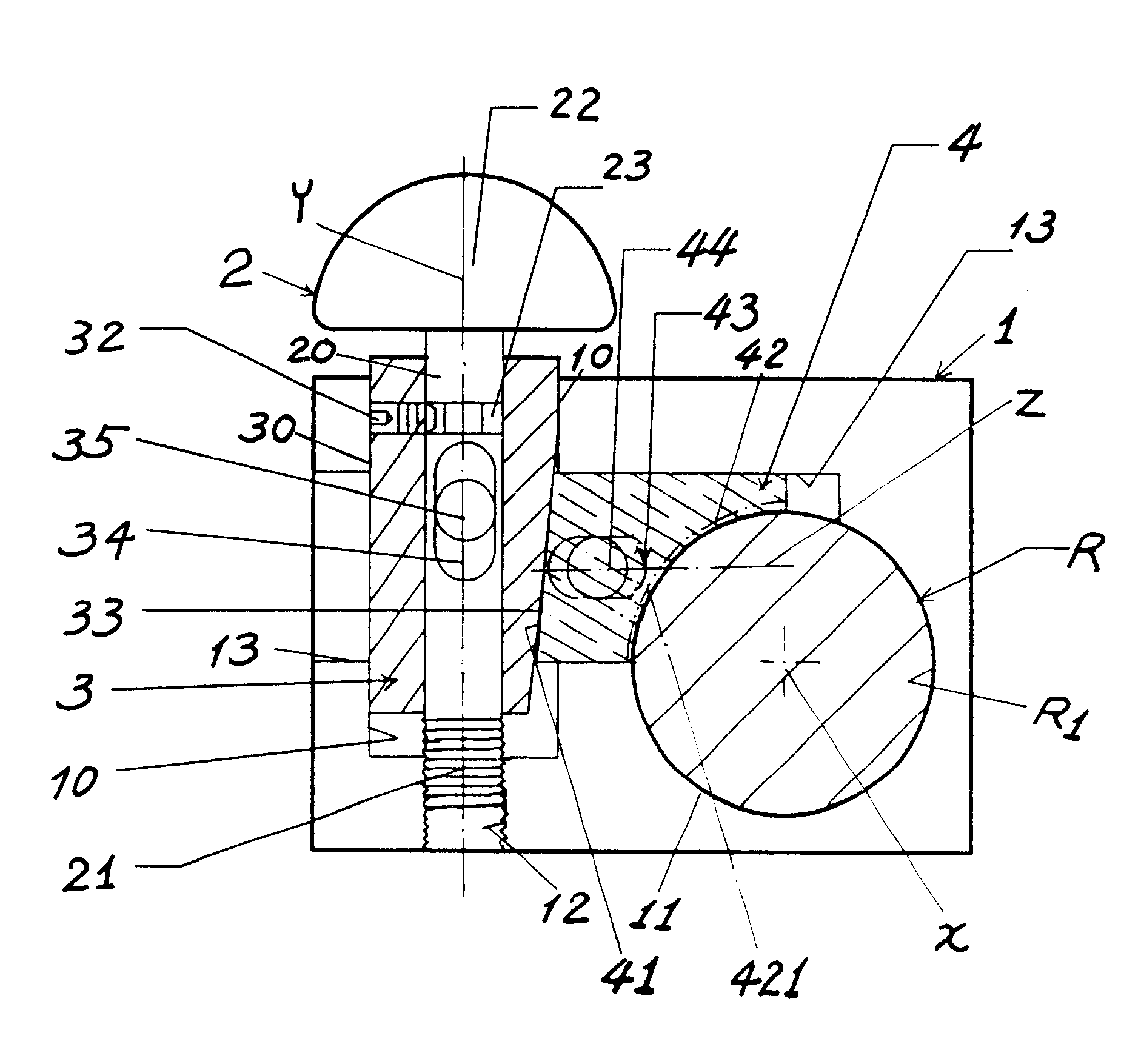
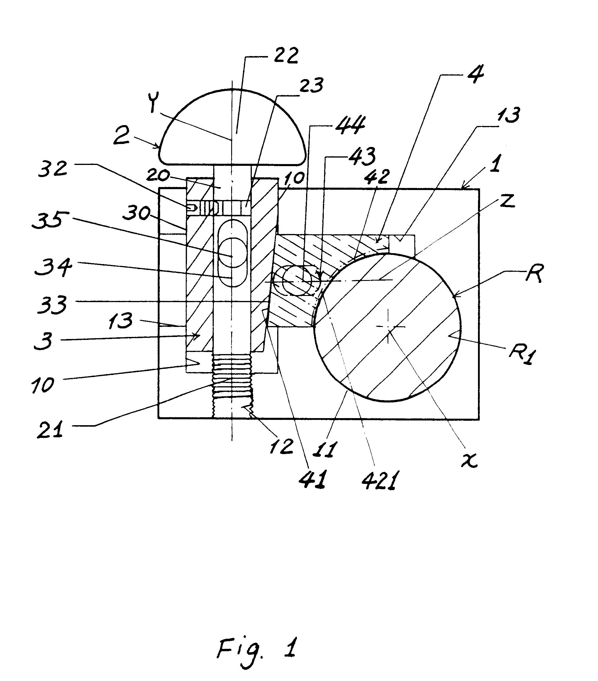
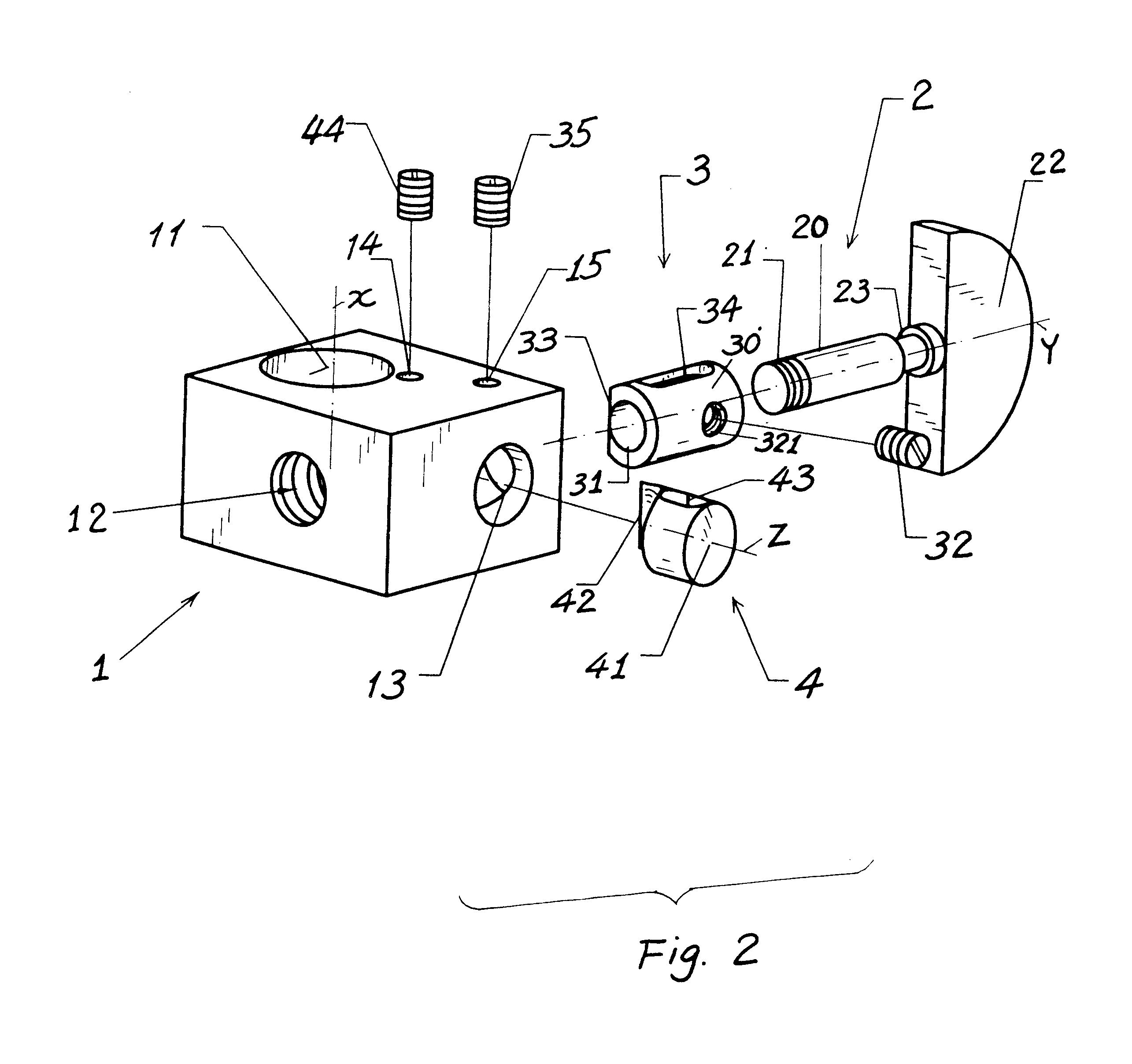
As shown in FIGS. 1.about.3, the fastening means of the present invention comprises: a holding base 1 capable of sliding or rotating on a rod or rod-like fixture R; a driving bolt 2 rotatably engageable with the holding base 1; a thrusting block 3 rotatably coupled with the driving bolt 2 and reciprocatively held in the holding base 1; and a follower block 4 tangentially engageable with the thrusting block 3 and reciprocatively moving in the holding base 1; whereby upon rotating the driving bolt 2, the thrusting block 3 forwarding simultaneously to thrust the follower block 4, then to interfere in the surface of the rod R for firmly fastening the rod R in (or with) the holding base 1.

The rod 1 may be referred to a column, bar, beam, tubular cylinder, or any other rod-like fixture, formed as cylindrical shape or other shapes, not limited in the present invention. However, the cylindrical rod is most preferable to be used in this invention.

The holding base 1 may be integrally formed w...


PUM


Abstract

A fastening device includes a holding base capable of sliding or rotating on a rod or column, a driving bolt rotatably coupled with a thrusting block rotatably engaged in the holding base having a driving wedge face formed on the thrusting block, and a follower block movably reciprocating in the holding base having a follower wedge face formed on the follower block and tangentially engageable with the driving wedge face of the thrusting block; whereby upon a rotation of the driving bolt to inwardly push the thrusting block in the holding base, the follower block will be thrusted by the driving block to interfere in a rod (or column) surface for quickly, ergonomically and firmly fastening the rod (or column) within the holding base.

Description

BACKGROUND OF THE INVENTIONA conventional fastening device as shown in FIG. 4 includes: a collar C capable of sliding or rotating on a cylindrical rod or column R, and a bolt having a screw portion S engaged with the collar to compress the rod R upon rotation of the knob K formed on an outer end of the bolt.However, such a conventional fastening device has the following drawbacks: 1. The screw portion S has a single-point compressing on the rod R, easily causing loosening or rotation of the rod unstably held within the collar. 2. The screw tip may stick or injure the rod surface after heavily driving the knob K for firmly fastening the collar on the rod. 3. Great force is required for firmly fastening the collar on the rod, easily causing tiredness to the operator or user.Another conventional fastening device as shown in FIG. 5 includes a clamp C' for fastening the rod R upon driving of the knob K of a bolt having a screw portion S coupling the clamp. Even the contact surface betwee...

Claims


Application Information

Patent Timeline
Patent Type & Authority Patents(United States)
IPC IPC(8): F16B2/02F16B2/18
CPCF16B2/18Y10T403/535Y10T403/7067
Inventor WANG, SHYH-JENLIN, MING-RENWANG, SHYH-YAUCHEN, SU-CHEN
Owner WANG SHYH JEN
Why Eureka
Try Eureka