Use of texture memory for WX scan conversion

a texture memory and scan technology, applied in the field of radar display systems, can solve the problems of high associated cost of conventional radar display systems, failure to take advantage of the hardware and software capabilities of general purpose graphics hardware included in most computer systems, and high cost of dedicated hardwar

Inactive Publication Date: 2003-09-16
HONEYWELL INT INC
View PDF15 Cites 22 Cited by
  • Summary
  • Abstract
  • Description
  • Claims
  • Application Information

AI Technical Summary

Problems solved by technology

However, the above-discussed conventional radar display system has a high associated cost due to the various hardware components required, and fails to take advantage of hardware and software capabilities of the general purpose graphics hardwa

Method used


Image

  • Use of texture memory for WX scan conversion
  • Use of texture memory for WX scan conversion
  • Use of texture memory for WX scan conversion

Examples


Embodiment Construction

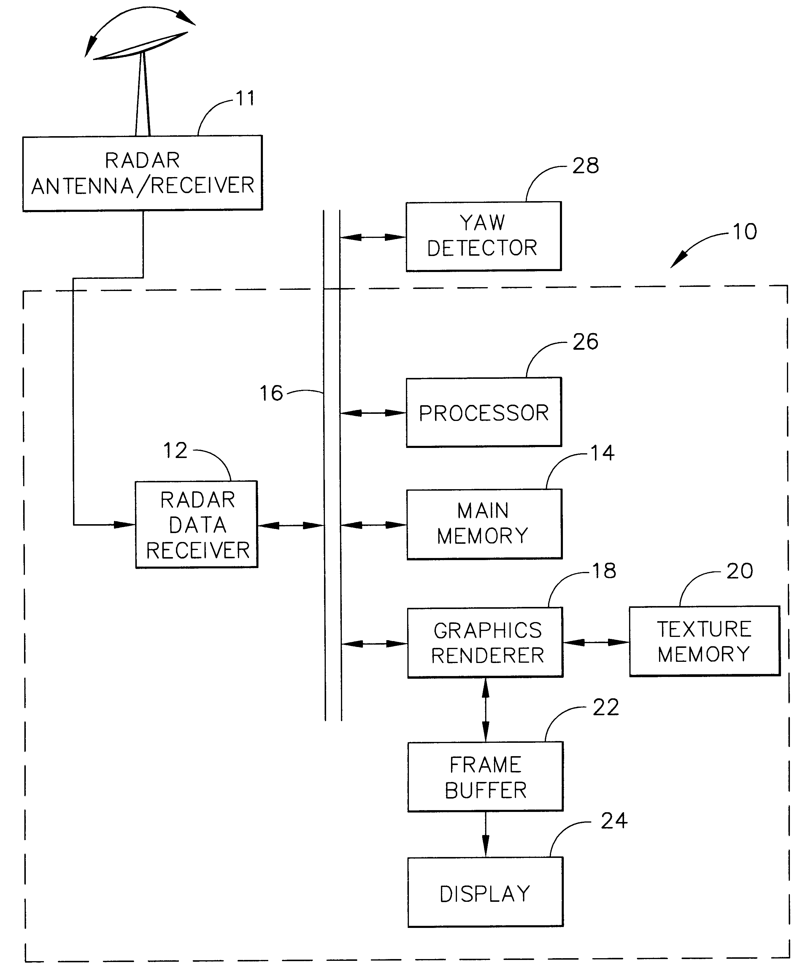
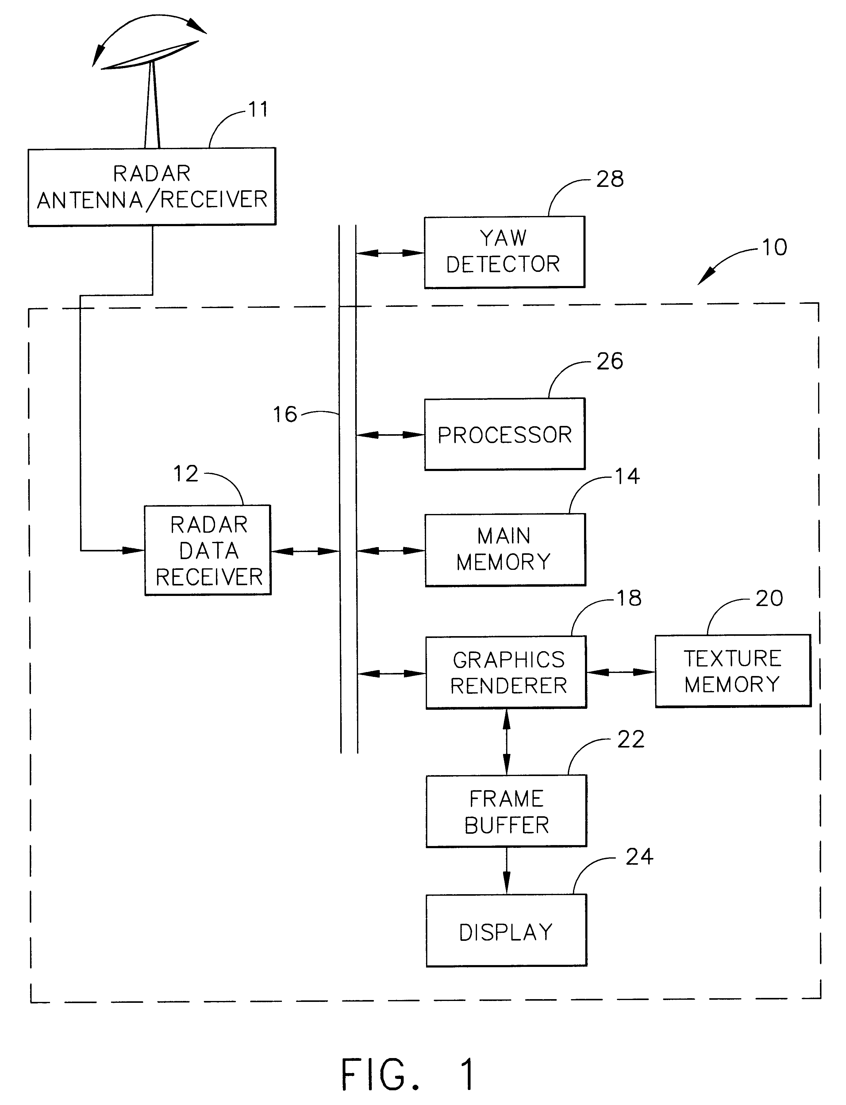
Referring now to the drawings in which like numerals reference like parts, FIG. 1 shows a display system 10 of the present invention that utilizes texture memory for radar scan conversion. The display system 10 is implemented within, for example, an aircraft navigational display system and is in electronic communication with other components of the navigational display system, such as a compass or a yaw detector 28. However, the display system can be implemented within any radar system in which a scaled color display output is desired.

The radar display system 10 includes several hardware and software components as follows. A radar antenna and receiver / processor (radar antenna / receiver) 11 that is part of, for example, an aircraft weather radar system is in communication with a radar data receiver 12. A main memory 14 is in communication with the radar data receiver 12 via a system bus 16. A graphics renderer 18 is in communication with a texture memory 20, a frame buffer 22 and the ...


PUM


Abstract

A radar display system (10) according to the present invention generates textured radar display data by utilizing a direct memory access receiver (12) to receive radially scanned radar data, to convert the radially scanned radar data into range bin data sets, and to store the range bin data sets. A graphics renderer (18) stores the set of range bin data sets in a texture memory (20) as a plurality of rectangular textures, and bit maps the rectangular textures to a series of display triangles in a frame buffer (22). The graphics renderer (18) colors the display triangles in accordance with the rectangular textures by performing a bi-linear interpolation of the color and warps the display triangles in accordance with the size of a display (24).

Description

1. Field of the InventionThe present invention relates generally to radar display systems and, more particularly, to a system for displaying radar images with other symbology.2. Description of the Related ArtA conventional radar display system utilizes various hardware components to generate a colored radar display image. A receiver receives radar energy from a radar antenna and converts the radar energy into radial intensity values from one radial (angle) of the radar antenna during a radar scan in polar coordinate format. Successive radials make up a complete scan. In order to display these radial intensity values, a scan converter converts the radial intensity values from polar coordinate format to Cartesian coordinate format, and converts each of the radial intensity values into color information. The scan converter stores the values and the color information to permit display of a complete image at one time despite the slow scan of the radar antenna. A scaler subsequently compr...

Claims


Application Information

Patent Timeline
IPC IPC(8): G01S7/298G01S7/295G01S13/00G01S13/95G01S7/14G01S7/04G01S7/22G06T11/00
CPCG01S7/298G06T11/001G01S7/14G01S7/22G01S13/951Y02A90/10
Inventor FISHER, PAUL A.HANCOCK, WILLIAM R.MCCULLOUGH, SUSAN L.
Owner HONEYWELL INT INC
Why Eureka
Try Eureka