Packet buffer apparatus and method

a technology of packet buffering and buffering, applied in the direction of cell components, instruments, electrochemical generators, etc., can solve the problems of long read operation time, high overhead, and often inability of the bus to get a read done in one transaction

Active Publication Date: 2010-10-19
MARVELL ASIA PTE LTD
View PDF2 Cites 86 Cited by
  • Summary
  • Abstract
  • Description
  • Claims
  • Application Information

AI Technical Summary

Benefits of technology

[0006]In one embodiment, a method of managing and buffering packet data for transmission out of a host comprises caching descriptor ring data pushed in from a host memory into a descriptor ring cache, where the descriptor ring data comprises one or more data packet descriptors each corresponding to a data packet to be transmitted and where the descriptor ring data is written by the host into the descriptor ring cache, processing the descriptor ring data cached in the descriptor ring cache to read a data packet descriptor from the descriptor ring data, initiating a direct memory access transfer from the host to read the data packet corresponding to the read data packet descriptor to a data transmission buffer, caching the requested data packet from the host memory into the data transmission buffer, where the requested data packet is written by the direct memory access into the data transmission buffer in response to the direct memory access transfer from the host, transmitting the cached data packet out of the data transmission buffer, and writing a return pointer to the host memory indicating that the data packet descriptor has been read and the corresponding data packet has been transmitted.
[0007]In another embodiment, a method managing and buffering packet data for transmission to a host comprises caching descriptor ring data pushed in from a host memory into a descriptor ring cache, where the descriptor ring data comprises one or more data packet descriptors each corresponding to a data packet to be received and where the descriptor ring data is written by the host into the descriptor ring cache, caching data packets for transmission to the host memory into a data reception buffer, reading data from the data reception buffer according to a data packet descriptor retrieved from the descriptor ring cache, initiating a direct memory access transfer to write the data packet to a data reception queue within the host memory, and writing a return pointer to the host memory indicating that the data packet has been written to the host memory.

Problems solved by technology

As a result, the host memory read operations took a long time as compared to the host memory write operations.
Read operations therefore took a lot of overhead, which is undesirable when buffering time-sensitive data packets (low latency), such as audio, video, etc.
Even when using a fast bus for time-sensitive data packets, the bus was often unable to get a read done in one transaction.
This caused even a single read to be time consuming.
Read operations also caused the host to have to stop and wait for a data return, thereby creating slow and inefficient processing, and thus lost bandwidth due to unnecessary overhead traffic.
Polling the ownership bits further caused lost bandwidth and unnecessary traffic.
This constant changing of ownership bits were therefore an inefficient and wasteful use of bus bandwidth.
In a multi-processor and / or multi-thread system, service interrupts to the host caused all processors or threads to be activated to determine which interrupts had been enabled, which tended to increase processor overhead and reduce the efficient use of the processors or threads.
However, there are few implementations that try to solve issues such as slow response time, high processor overhead, host / hardware polling, long latency due to double or even triple layers of lookup and translation, and the utilization of a large cache to store the descriptor table and caching.
At the same time, these few implementations include control logic which may be quite complicated and cause the die size of the chip to be large and increase verification time.

Method used


Image

  • Packet buffer apparatus and method
  • Packet buffer apparatus and method
  • Packet buffer apparatus and method

Examples


Embodiment Construction

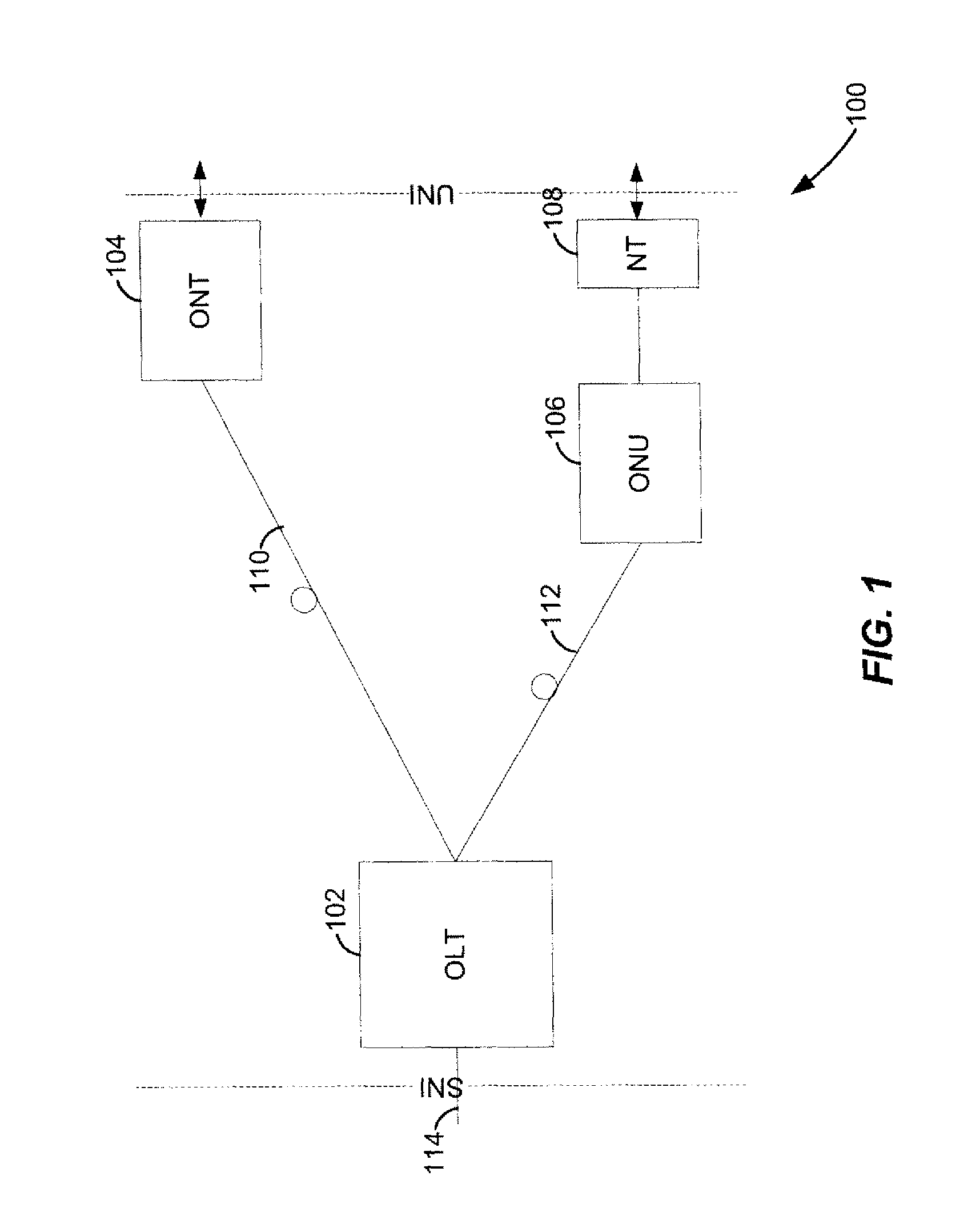
[0018]FIG. 1 is a block diagram of an example passive optical network 100 that includes an optical line termination (OLT) 102 coupled to an optical network terminal (ONT) 104 and an optical network unit (ONU) 106. Generally, the passive optical network 100 is a point-to-multipoint network, where the OLT 102 is provided as a service node interface, for example at a server or service provider, such as an interne service provider, television service provider, telephony service provider or other provider of network services. The ONT 104 and / or ONU 106 are each provided as an user node interface, for example at or near an end user. While the OLT 102 may be provided at the service provider site, the OLT 102 may also be provided as one of several OLTs within a distributed network, where each OLT is associated with corresponding ONUs 106 and / or ONTs 104.

[0019]As shown in FIG. 1, the OLT 102 is communicatively coupled to the ONT 104 via an optical fiber 110, and communicatively coupled to th...


PUM


Abstract

In managing and buffering packet data for transmission out of a host, descriptor ring data is pushed in from a host memory into a descriptor ring cache and cached therein. The descriptor ring data is processed to read a data packet descriptor, and a direct memory access is initiated to the host to read the data packet corresponding to the read data packet descriptor to a data transmission buffer. The data packet is written by the direct memory access into the data transmission buffer and cached therein. A return pointer is written to the host memory by the direct memory access indicating that the data packet descriptor has been read and the corresponding data packet has been transmitted. In managing and buffering packet data for transmission to a host, descriptor ring data is pushed in from a host memory into a descriptor ring cache and cached therein. Data packets for transmission to the host memory are received and cached in a data reception buffer. Data is read from the data reception buffer according to a data packet descriptor retrieved from the descriptor ring cache, and the data packet is written to a data reception queue within the host memory by a direct memory access. A return pointer is written to the host memory by the direct memory access indicating that the data packet has been written.

Description

CROSS-REFERENCES TO RELATED APPLICATIONS[0001]The present application claims the benefit of U.S. Provisional Application No. 60 / 868,216, entitled “PACKET BUFFER ARCHITECTURE,” filed on Dec. 1, 2006, which is hereby incorporated by reference herein in its entirety.FIELD OF TECHNOLOGY[0002]The present disclosure relates generally to packet buffering and handling, and more particularly, to packet buffering and handling within a gigabit passive optical network.DESCRIPTION OF THE RELATED ART[0003]The traditional descriptor ring architecture has been used widely in the communication world. A traditional descriptor ring architecture set up a descriptor ring in the host memory, which, in combination with related Direct Memory Access (DMA) hardware, controlled the packet buffering. Firmware or software configured the set of descriptor rings. The hardware polled into the host constantly to see if the descriptor was ready for use by the hardware.[0004]Previous data packet buffering and handlin...

Claims


Application Information

Patent Timeline
Patent Type & Authority Patents(United States)
IPC IPC(8): G06F15/167
CPCH01M4/92H01M4/925H01M4/926H01M2008/1095Y02E60/50
Inventor CHIANG, JOHN M.JOHNSTON, CESAR A.
Owner MARVELL ASIA PTE LTD
Why Eureka
Try Eureka