Digital signal processor decoding of convolutionally encoded symbols

a digital signal processor and convolutional encoder technology, applied in the field of communication techniques, can solve problems such as noise, significant amount of memory needed to specify each state, and noise between the two signals

Inactive Publication Date: 2003-09-16
RENESAS ELECTRONICS AMERICA
View PDF15 Cites 12 Cited by
  • Summary
  • Abstract
  • Description
  • Claims
  • Application Information

AI Technical Summary

Problems solved by technology

Of course, the received signal differs from the signal that is transmitted and the difference between the two signals is called noise.
Unfortunately, a significant amount of memory is needed to specify each state.
In implementing a Viterbi decoder, two practical difficulties are present: computational load and the demand for memory.
Maintaining long histories for each of the 256 states of an IS-95 decoder, for example, can require large amounts of memory.
However, such truncations introduce errors and, in order to avoid excessive errors with this approach, history lengths of 4-5 times the constraint length are generally recommended.
This trace-back operation can be computationally intensive.
Forcing the decoder to make premature decisions may still be necessary, but this will be because the total memory describing the transition history has been exhausted.

Method used


Image

  • Digital signal processor decoding of convolutionally encoded symbols
  • Digital signal processor decoding of convolutionally encoded symbols
  • Digital signal processor decoding of convolutionally encoded symbols

Examples


first embodiment

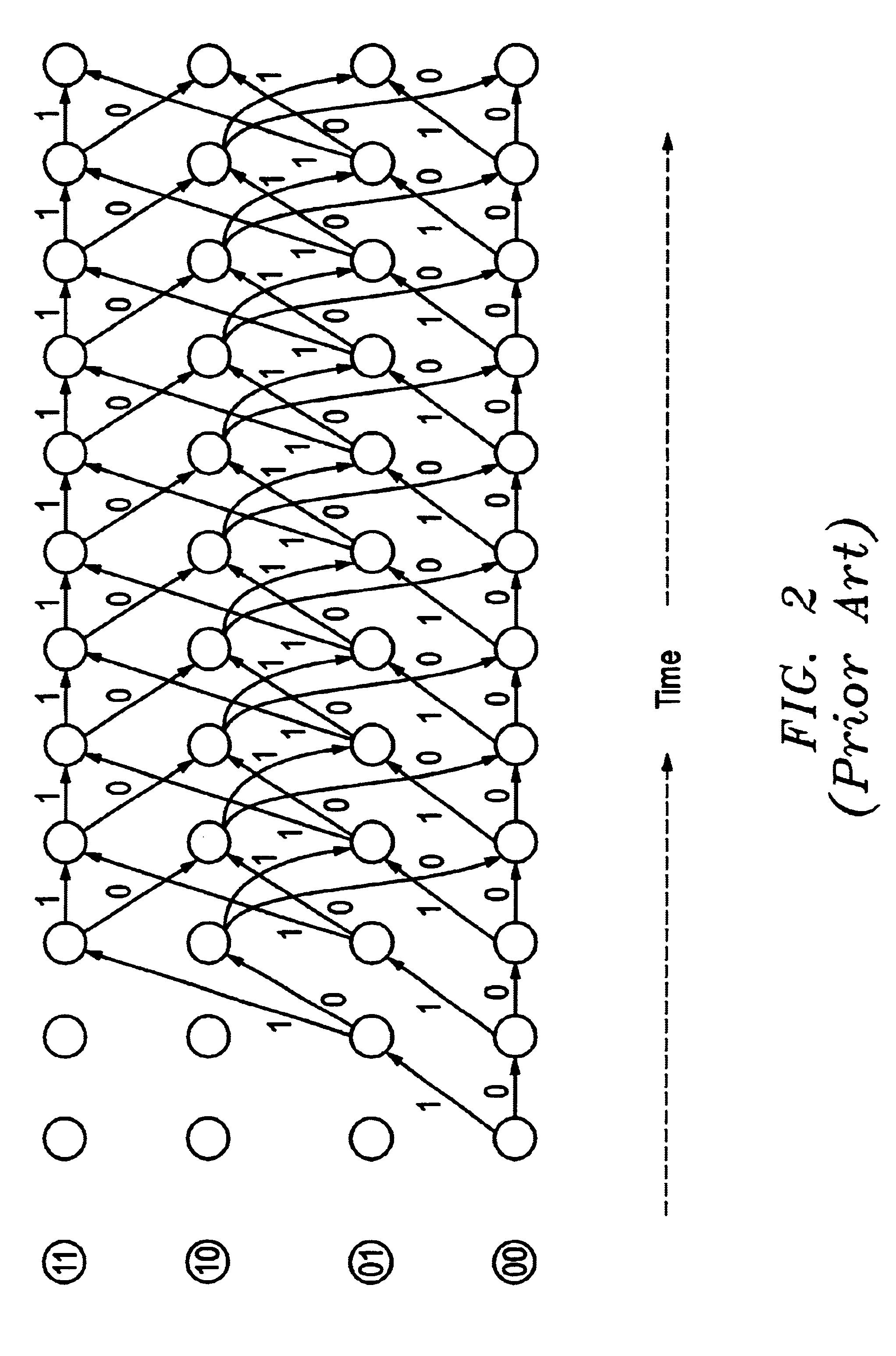
In either embodiment, the paths through the other states are handled analogously. Likewise, in a decoder with more states (e.g., the IS-95 decoder with 256 states), the operation is exactly the same for each state. As will be clear to those skilled in the art of Viterbi decoders, it is possible to conserve memory in the trellis decoder unit and simplify computations by operating on pairs of states together so as to update the path metrics, history and (in the case of the first embodiment) index values for the two states at the same time, keeping the same memory locations. This implies that the data associated with a given state moves from one location to another from one time interval to another; however, at the end of (constraint_length-1) steps all of the data are back to their original locations. This observation considerably simplifies the production of the tables that are output to the history tracker unit.

Each time a table of metrics arrives, the trellis decode unit must updat...

embodiment 1

H(lo).rarw.H(hi) and in embodiment 1, I(lo).rarw.I(hi)

(2) PM(lo).rarw.PM(lo)+TR(lo,lo)

PM(hi).rarw.PM(lo)+TR(lo,hi)

H(hi).rarw.H(lo) and in embodiment 1, H(hi).rarw.H(lo)

(3) PM(lo).rarw.PM(hi)+TR(hi,lo)

PM(hi).rarw.PM(lo)+TR(lo,hi)

H(lo).rarw.H(hi) and in embodiment 1, I(lo).rarw.I(hi)

H(hi).rarw.H(lo) and in embodiment 1, H(hi)+H(lo)

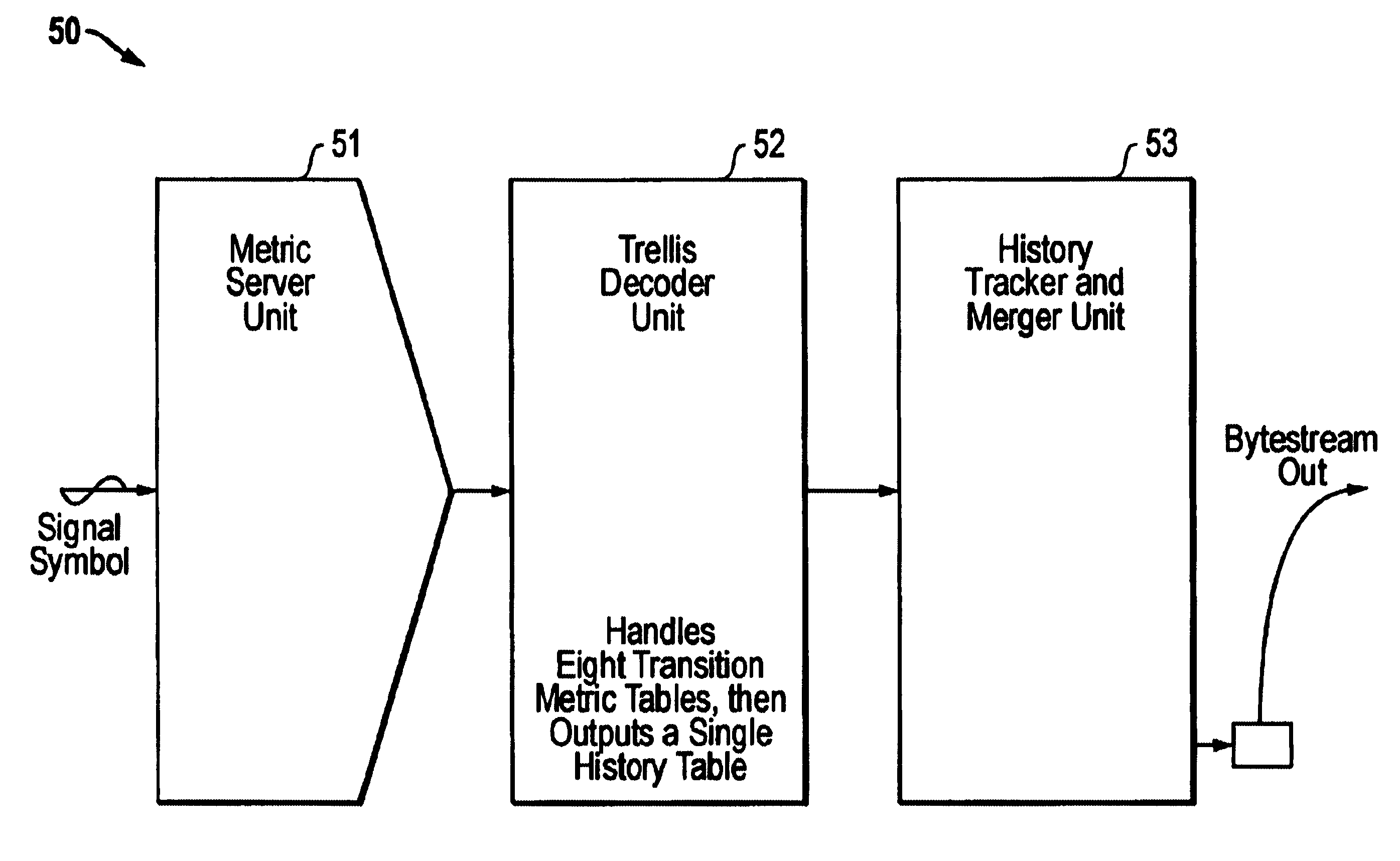
The trellis decoder unit 52 maintains only a single copy of the path metric, index and history for each state, though these values change with time. Using the four state decoder as an example, after updating the path metrics, indexes and history data at time t.sub.2n+4, the trellis decoder passes a table of data to the history tracker and merger unit 53 which will enable the unit to compute, for the paths that survive at time t.sub.2n+4, the state S.sub.2n from the state S.sub.2n+2. To describe the computation of this output data it is useful to simplify our notation. At time t.sub.2n+4, the only information remaining in the trellis decoder relates to time t...

second embodiment

The second embodiment, the operation of which was described with respect to FIGS. 15, 16, 17A, 17B and 17C, provides an improved interface between the processor unit and the peripheral unit. In particular, this embodiment provides a trail compression that results in a simplified decoding procedure.


PUM


Abstract

In one embodiment, a file of all the initial states (or their equivalents) and the nth surviving states associated with the initial states is stored along with the path metric. The initial states (or their equivalents) are an index to a previous file. A.new file or files are then generated. An appropriate criterion is utilized to select a final surviving state. The path can be traced back through a plurality of files and the "most likely" path determined. The identifying binary numbers of the final states of each file and the binary numbers of an original initial state determine the "most likely" sequence of convolutionally-encoded symbols received by the decoder. The convolutional decoding can be implemented with a digital signal processor and a dedicated peripheral unit. This apparatus can provide an efficient use of memory for the possible decoding paths.

Description

1. Field of the InventionThis invention relates generally to communication techniques and, more particularly, to the decoding of digital signals in a communication system. In the communication system envisioned by the present invention, each bit of information has been encoded in a multiplicity of transmitted signals. The resulting signals are generally referred to as convolutionally encoded symbols.2. Description of the Related ArtCommunications channels in general and digital wireless communications in particular must counteract noise which may obliterate individual transmitted symbols. Conceptually, there are two approaches to this problem: one, by introducing redundancy and another, by smearing the transmitted information over multiple symbols. These approaches are not entirely separate since any redundancy makes it easier to spread the information over a plurality of signals, but neither are the two approaches identical.Convolution codes are often used to implement the smearing...

Claims


Application Information

Patent Timeline
IPC IPC(8): H03M13/23H03M13/00
CPCH03M13/23
Inventor COHEN, PAUL E.
Owner RENESAS ELECTRONICS AMERICA
Why Eureka
Try Eureka