Dripless plunger

a plunger and plunger technology, applied in the direction of rigid containers, packaging, transportation and packaging, etc., can solve the problems of affecting the use of the plunger, and causing the plunger to collapse, and the liquid remaining on the plunger will often drip onto the floor, carpet or underlying surface, and messy and inconvenien

Inactive Publication Date: 2003-09-23
BROWN OWEN (I) (US)
View PDF9 Cites 14 Cited by
  • Summary
  • Abstract
  • Description
  • Claims
  • Application Information

AI Technical Summary

Benefits of technology

It is an object of the present invention to provide a plunger that includes an integral cover that prevents drippage and thereby avoids inadvertent soiling of floors, carpets, and underlying surfaces as the plunger is removed from the location of its use to its storage location.

Problems solved by technology

During use, the cup is positioned over a clogged drain to form a seal thereabout, and the handle is then depressed causing the cup to collapse and apply pressure to the obstruction in the drain.
A problem with all of the above-mentioned plunger designs is that, as the plunger is removed from the location of its use to a storage location, liquid remaining on the plunger will often drip onto the floors, carpets, or underlying surfaces during transport.
However, this solution requires that a separate part to be held during transport and is messy and inconvenient.

Method used


Image

  • Dripless plunger
  • Dripless plunger
  • Dripless plunger

Examples


Embodiment Construction

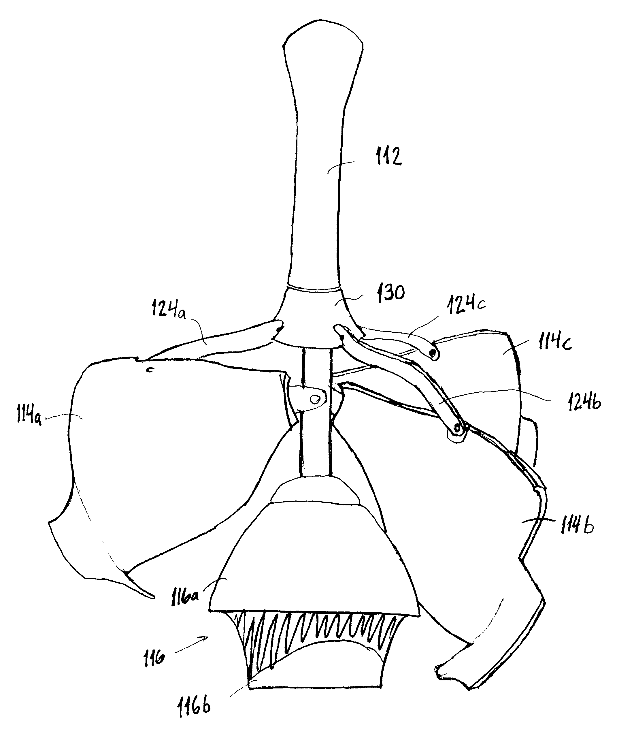
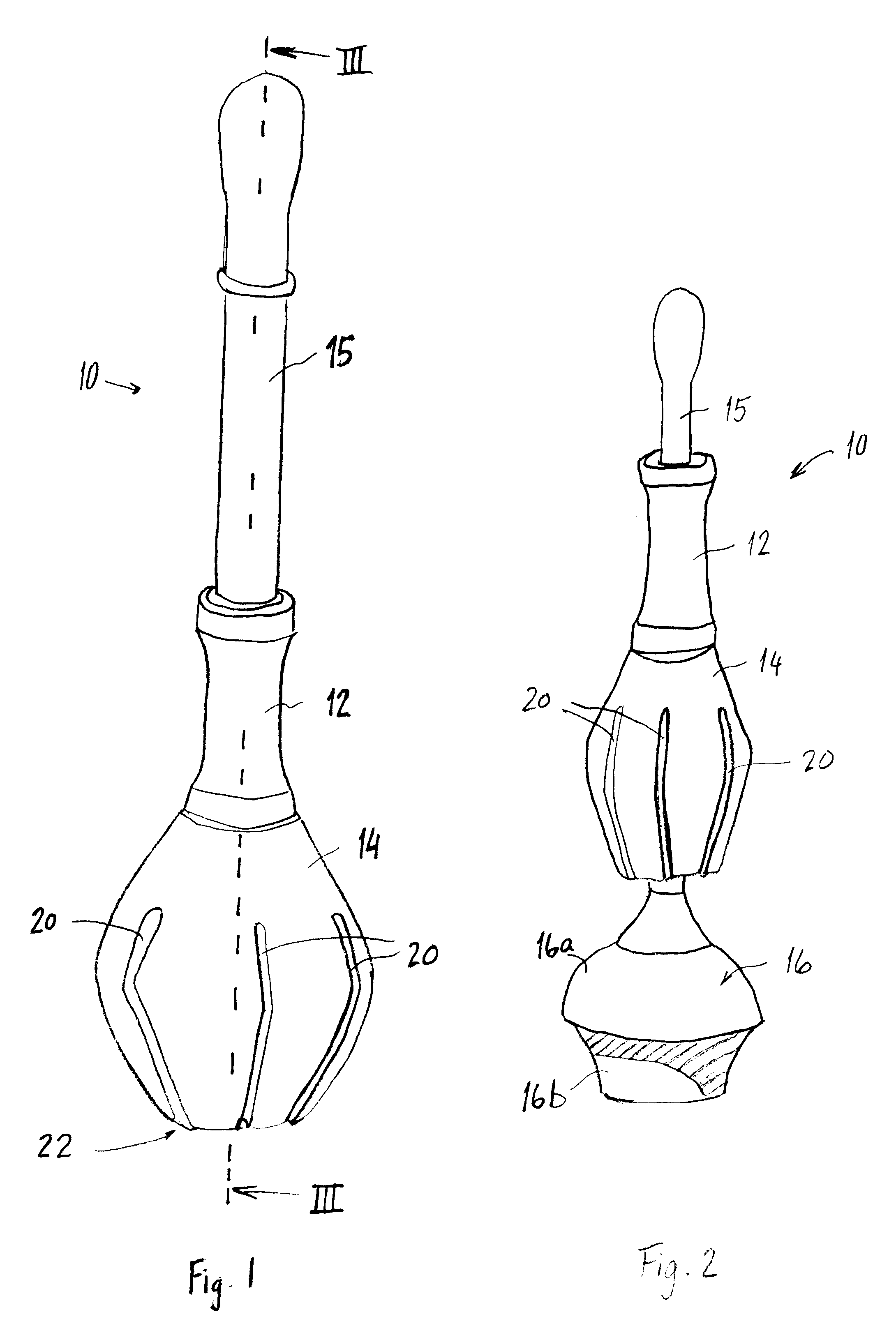
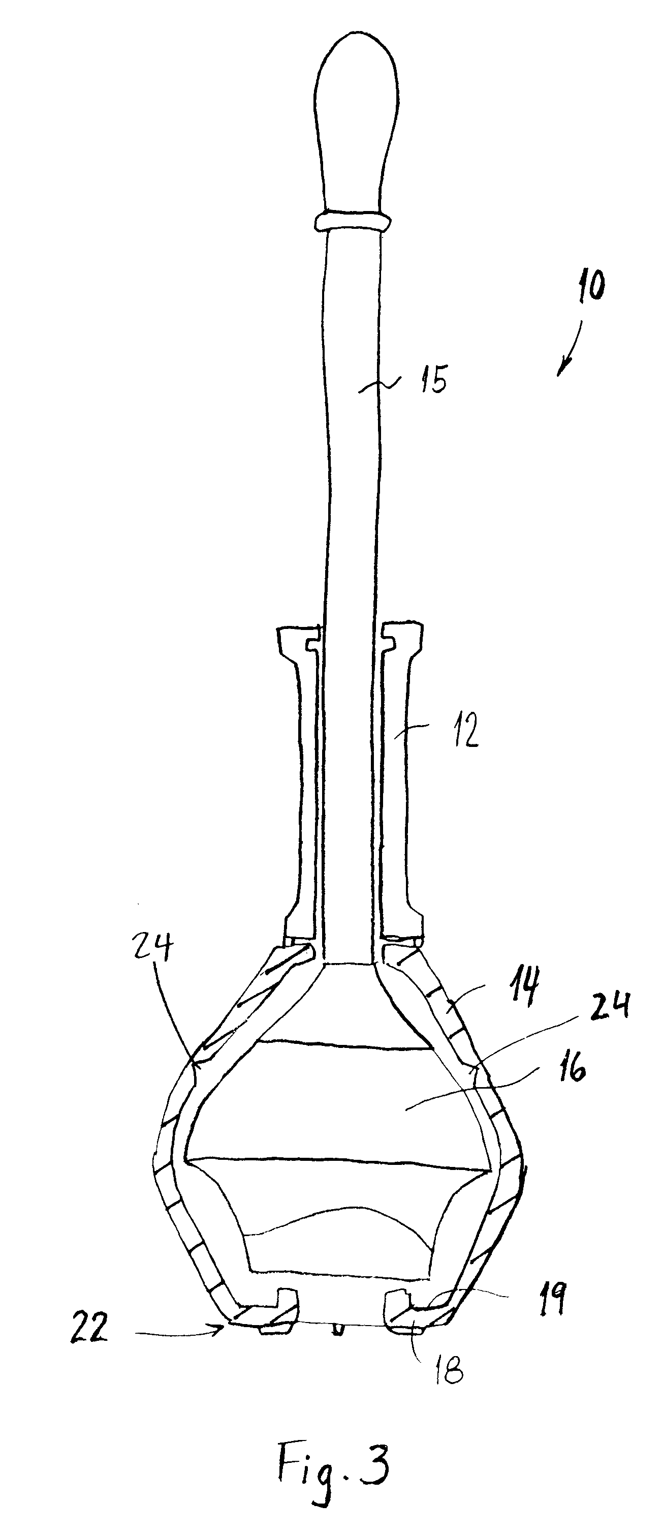
A plunger 10 constructed in accordance with a first embodiment of the present invention is shown in FIGS. 1-4. The plunger 10 is seen in its closed position in FIG. 1 and in its open position in FIG. 2, and includes a shaft 15 having one end connected to a head 16. The head 16 and shaft 15 are used in a conventional manner to force liquid through a drain pipe to remove obstructions by forcing them through the pipe under the pressure created by deformation of the head. Thus, the head 16 is positioned to create a seal around the drain to be unclogged, and the shaft 15 is advanced toward the head 16 to collapse the head and create a surge of pressure in the drain pipe to be unclogged. Accordingly, the head 16 must be formed of a material, such as rubber, that is flexible and that is self-restoring to its original shape when the advancing force on the shaft 15 is removed or discontinued. The shaft, on the other hand, must be formed of a rigid material such, for example, as metal, wood, ...


PUM


Abstract

A dripless plunger includes a head connected to a shaft and a cover movable under user control of an actuator on the shaft from a closed position in which the cover overlies the head to prevent drippage from the head after use of the plunger to clear a clogged drain, and an open position in which the cover is moved to a position remote from the head to permit the head to be placed sealingly about the drain and deformed for forcing water through the drain to unclog the same.

Description

1. Field of the InventionThe present invention relates to a plumbing device for clearing obstructions from toilets and drain pipes and the like which includes an integrated cover to prevent drippage of liquids from the plunger after use.2. Description of the Related ArtConventional hand-operated plungers include a resiliently deformable cup or head attached to a handle. During use, the cup is positioned over a clogged drain to form a seal thereabout, and the handle is then depressed causing the cup to collapse and apply pressure to the obstruction in the drain. The cup portion of the plunger has been designed in many different configurations for various applications and to increase the applied pressure. For example, U.S. Pat. No. 1,193,476 (Block) discloses a plunger having a basic cup-shaped design with a reinforced rim; U.S. Pat. No. 5,974,596 (Strzok) discloses a plunger device having an inner cavity and an outer cavity for applying pressure to the obstruction; U.S. Pat. No. 6,14...

Claims


Application Information

Patent Timeline
Patent Type & Authority Patents(United States)
IPC IPC(8): E03C1/12E03C1/308E03C1/30A47K11/10E03D9/00
CPCE03C1/308E03D1/34E03D9/00
Inventor BROWN
Owner BROWN OWEN (I) (US)
Why Eureka
Try Eureka