

Brake hose
a technology of brake hoses and hoses, applied in the direction of mechanical equipment, layered products, chemistry equipment and processes, etc., can solve the problem of significant thread displacemen
Inactive Publication Date: 2003-09-30
TOYODA GOSEI CO LTD
View PDF16 Cites 18 Cited by
- Summary
- Abstract
- Description
- Claims
- Application Information
AI Technical Summary
Benefits of technology
Because the fluid pressure transmitted in this fashion travels from the inner circumference area to the outer circumference area of the brake hose in a radial fashion, the fluid pressure diminishes per unit area as it travels to the outer circumference area, and the lower yarn layer in the inner circumference area of the brake hose receives a larger amount of expansion force than the upper yarn layer. As a result, where the lower yarn layer and the upper yarn layer are formed from yarn made of the same material, the yarn of the lower yarn layer receives a greater tensile force than the yarn of the upper yarn layer. This means that even where the first yarns bursts after receiving a large amount of tensile force, there is still some degree of margin or leeway before the second yarns bursts. In view of this fact, the percentage burden assumed by the lower yarn layer is set at 50-65% of the total burden. In other words, the percentage burden assumed by the second yarns is set to a value larger than in a conventional brake hose, while the burden assumed by the first yarns is reduced. Consequently, the burden on each individual strand of yarn becomes smaller, and the ultimate rupturing pressure that may be applied to the brake hose can be increased.
In the brake hose pertaining to the present invention, the lower yarn layer and the upper yarn layer formed around the inner tube rubber layer form two reinforcing yarn layers inside the rubber base, and give the brake hose sufficient strength to withstand the high pressure of the pressure fluid flowing within the flow path. Furthermore, the first yarns constituting the lower yarn layer includes an adhesive thin film formed via RFL processing and a rubber thin film. The rubber thin film adheres to the inner tube rubber layer and prevents yarn displacement, increases the solidity of the lower yarn layer by causing the strands of the first yarns to adhere to each other at areas where they overlap, which prevents the inner tube rubber layer from expanding due to internal pressure, thereby limiting the amount of cubical expansion of the brake hose and improving the feel of the brake. The adhesive thin film formed via RFL processing is formed in order to cause the first yarns to adhere to the rubber thin film formed from EPDM. In RFL processing, an adhesive thin film that operates as an adhesive and is formed mainly from resorcinol-formaldehyde-latex resin and rubber latex is applied to the surface of each yarn strand.
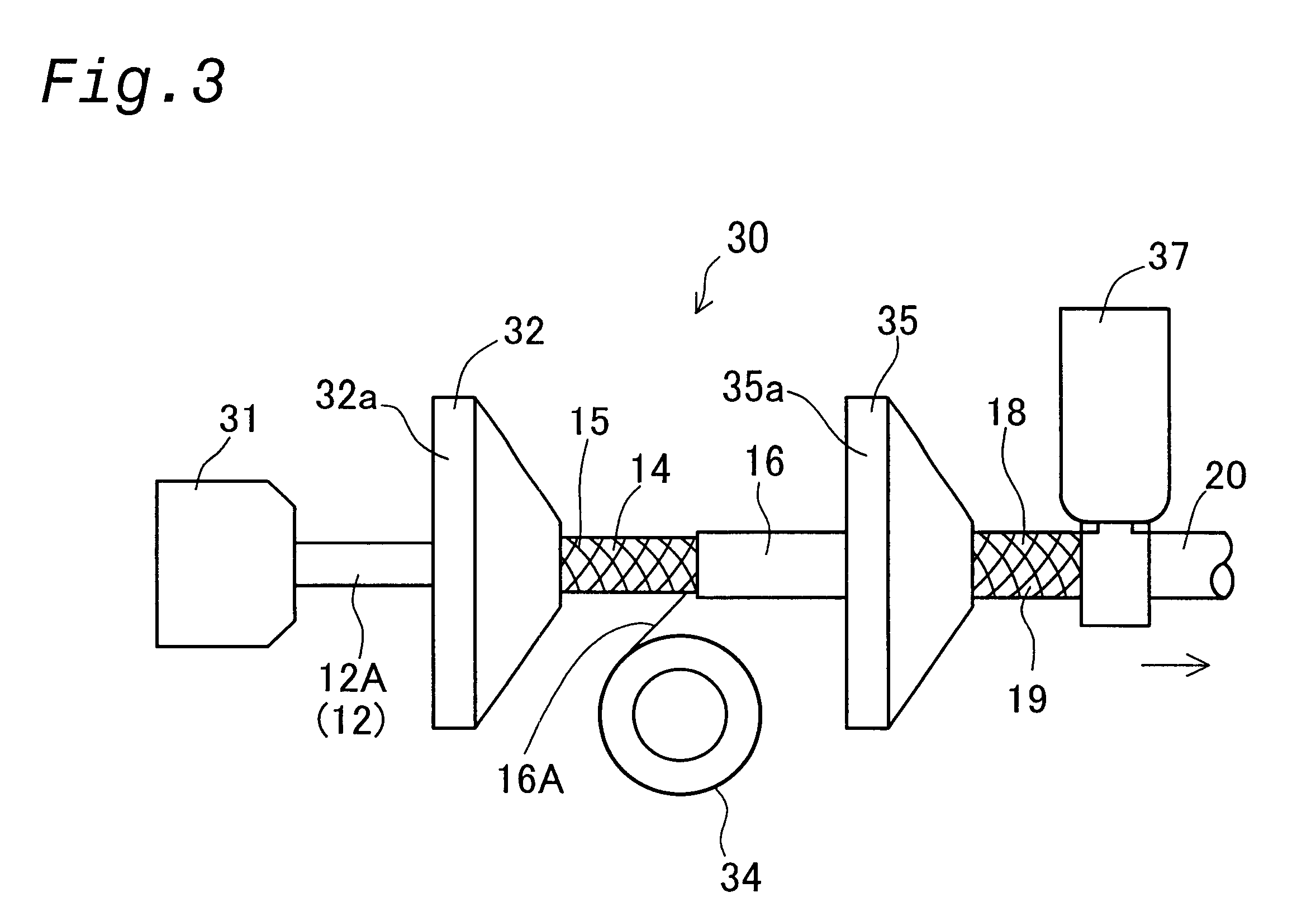
In a preferred embodiment of the first yarns, a filament bundle is formed by bundling together several hundred filament threads, over each of which is formed an undercoat layer using an epoxy primer process, and then forming over the filament bundle a layer formed via RFL processing and an EPDM layer. The lower yarn layer is then formed by braiding the first yarns around the inner tube rubber layer. In this case, because the filament threads adhere strongly to each other due to the undercoat layer, the penetration of air or brake fluid between the filament threads can be prevented more effectively.
In another preferred embodiment of the first yarns, a filament bundle is formed by bundling together filament threads, an undercoat is formed on the outer surface of the filament bundle using an epoxy primer process, and an adhesive thin film and a rubber thin film are sequentially formed over the undercoat layer. In this case, because the epoxy primer process is not performed for each individual filament thread, and is instead carried out for the filament bundle as a whole, manufacturing efficiency can be improved.
Problems solved by technology
This is because if the weight is less than 5%, the effect of preventing abrasion or displacement of the filament threads is not sufficiently obtained due to contact friction between the strands of the lower yarn 115a, while if the weight exceeds 30%, elastic deformation due to the rubber layer becomes large, resulting in significant thread displacement.
Method used
View moreImage
Smart ImageViewing Examples

Examples
Embodiment Construction
has been provided for the purpose of explaining the principles of the invention and its practical application, thereby enabling others skilled in the art to understand the invention for various embodiments and with various modifications as are suited to the particular use contemplated. The foregoing detailed description is not intended to be exhaustive or to limit the invention to the precise embodiments disclosed. Modifications and equivalents will be apparent to practitioners skilled in this art and are encompassed within the spirit and scope of the appended claims.
Login to View More PUM
| Property | Measurement | Unit |
|---|---|---|
| elongation | aaaaa | aaaaa |
| length | aaaaa | aaaaa |
| pressure | aaaaa | aaaaa |
Abstract
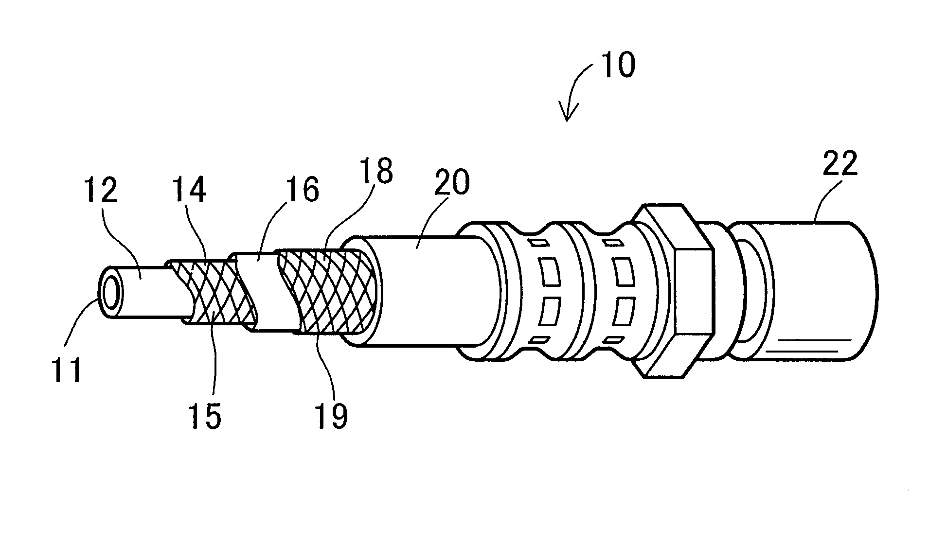
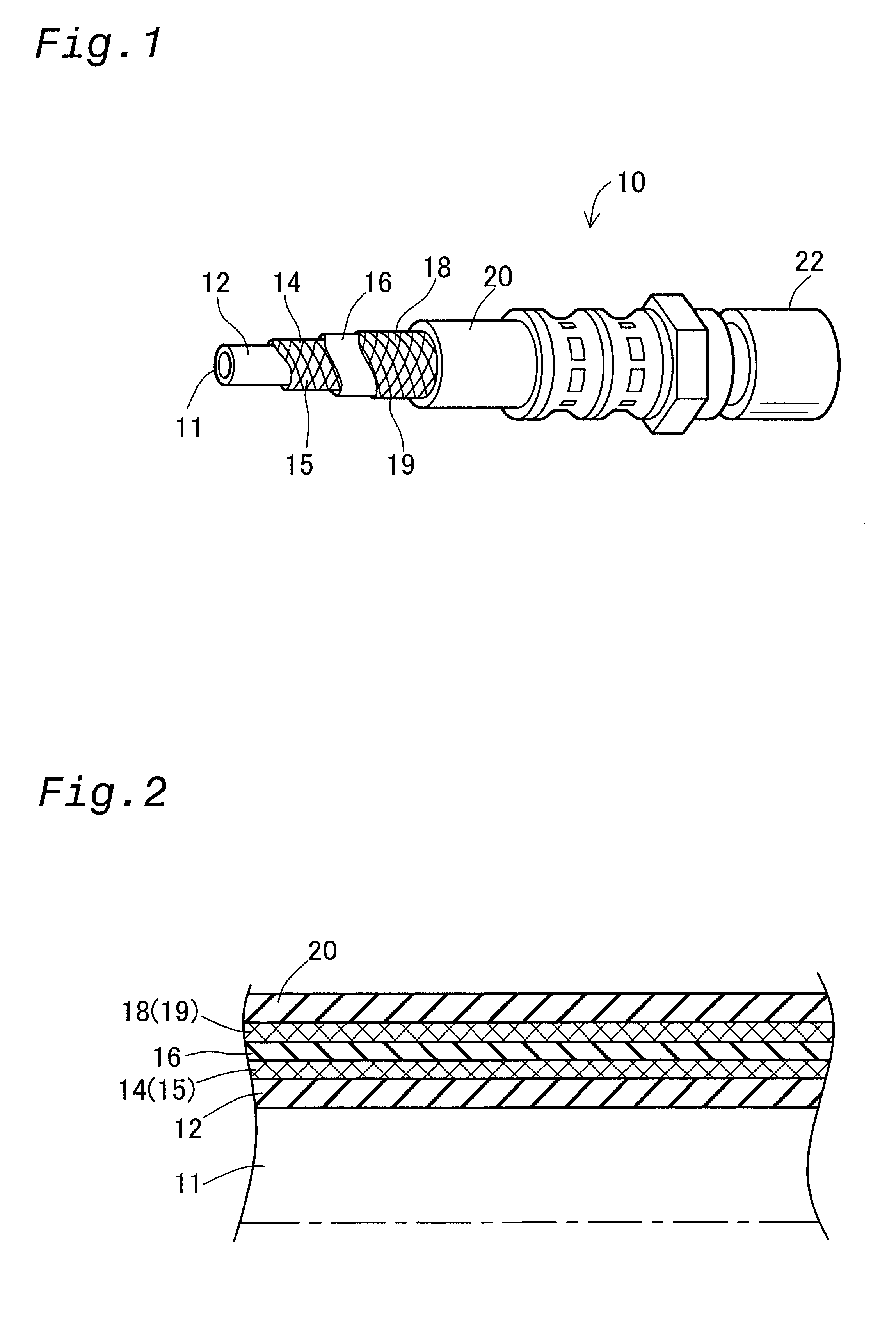
A brake hose includes two reinforcing layers in a rubber base. The brake hose comprises an inner tube rubber layer having a flow path for flowing fluid, a lower yarn layer formed by braiding first yarns around the inner tube rubber layer and an upper yarn layer formed by braiding second yarns around the lower yarn layer and a cover rubber layer covering the upper yarn layer. A lower yarn layer duty LD given by the equation, LD(%)=(LRP / PRP)x100, has a value of 50-65%,where LRP denotes an inner pressure at which a brake hose without the upper yarn layer and the cover would burst, and PRP denotes an inner pressure at which the brake hose would burst.
Description
This application claims the benefit of and priority from Japanese Applications No. 2001-360375 filed Nov. 27, 2001 and No. 2001-360379 filed Nov. 27, 2001, the content of which are incorporated herein by reference.1. Field of the InventionThe present invention pertains to a brake hose having two reinforcing yarn layers including a lower yarn layer and an upper yarn layer in a rubber base.2. Description of the Related ArtA brake hose known in the conventional art is shown in FIG. 16 (JP 06-201076A). FIG. 16 is a cross-section of the main components of a conventional brake hose 200. Because the brake hose 200 must have high resistance against brake fluid pressure, it is formed from several layers of rubber and fiber yarn. The brake hose 200 comprises an inner tube rubber layer 202, a lower yarn layer 204, an intermediate rubber layer 206, an outer yarn layer 208, and a cover rubber layer 210.The brake hose 200 is required to meet a higher pressure resistance standard than a coolant sy...
Claims
Login to View More Application Information
Patent Timeline
 Patent Type & AuthorityPatents(United States)
IPC IPC(8): B32B25/10B32B1/08B32B25/00B32B1/00F16L11/08
CPCB32B25/10F16L11/086
InventorMIZUTANI, SATOSHIFURUI, KENICHIROOGAWA, TAIZO
OwnerTOYODA GOSEI CO LTD