PDA antenna device for switching between antennae of a PDA unit based on detected use condition

a technology of pda unit and antenna device, which is applied in the direction of collapsible antenna means, differential interacting antenna combinations, and independent non-interacting antenna combinations. it is difficult to ensure sufficient antenna reliability of built-in antennas, and the decision standard for switching antennas becomes complicated. it contributes to the small size and weight of the pda

Inactive Publication Date: 2003-09-30
MITSUBISHI ELECTRIC CORP
View PDF14 Cites 40 Cited by
  • Summary
  • Abstract
  • Description
  • Claims
  • Application Information

AI Technical Summary

Problems solved by technology

Furthermore it is difficult to ensure sufficient antenna reliability of the built-in antenna 37 or the loop antenna 39 which should supplement reduced gain of the extendable / storable antenna 35.
Also the decision standard for switching the antennas becomes complicated due to the fact that the sensing means for the interference obstacle 38 is dependent on the material constituting the interference obstacle 38.
Hence it is possible to easily form an extremely thin second antenna and this contributes to the small size and weight of the PDA.

Method used


Image

  • PDA antenna device for switching between antennae of a PDA unit based on detected use condition
  • PDA antenna device for switching between antennae of a PDA unit based on detected use condition
  • PDA antenna device for switching between antennae of a PDA unit based on detected use condition

Examples


embodiment 1

above was explained on the basis of telephone communication and data communication being first and second use conditions respectively. However the invention is not limited in this respect. In other words, at least data communication / telephone communication carrying out data communication and telephone communication, or data processing of determined data before data communication or data communication / telephone communication operations may be considered as use conditions of the PDA apart from data communication and telephone communication.

Hence it is possible to designate data communication / telephone communication as a second use condition and data processing as a first or second use condition. And for the same reasons as outlined above, discrimination of the use condition is easily obtained and improved and stable antenna reliability can be easily ensured.

The discrimination of the use condition was explained on the basis of the input signal being due to user input operation. The inv...

embodiment 2

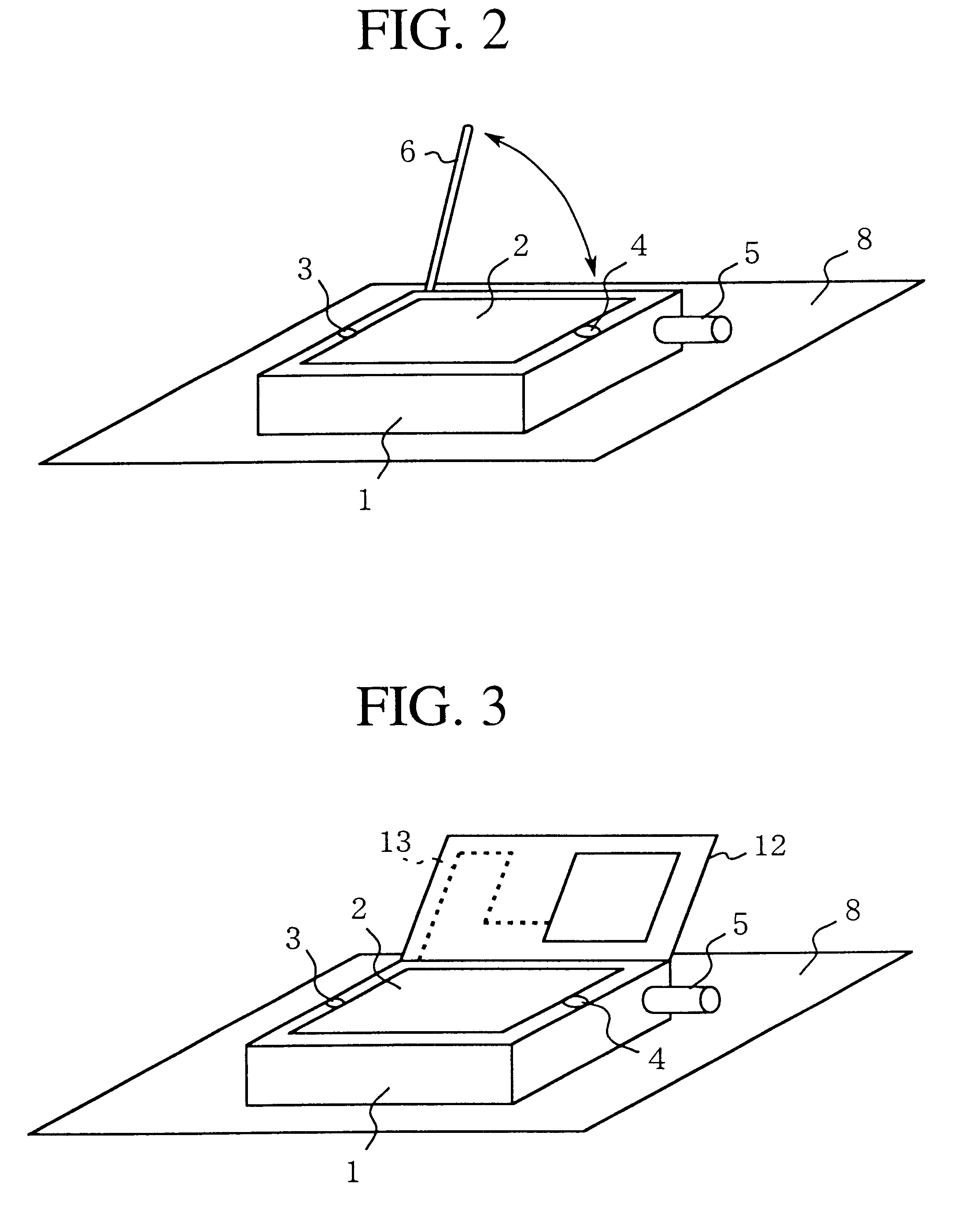
FIG. 3 is a perspective view showing the use condition during data communication of an antenna device for use with a PDA according to a second embodiment of the present invention. In the following explanation, elements similar to those already explained will be simply represented by similar numerals.

In FIG. 3 reference numeral 12 represents a thin sheet antenna installation cover, the orientation of which may be optionally changed with respect to the interference obstacle 8. In other words one end of the antenna installation cover 12 is held in an freely rotatable position with respect to the body 1 and may be placed in an optional stationary position.

13 is a cover antenna for data communication (second antenna) formed in a plane shape inside the antenna installation cover 12 by one of printing, deposition and transferal and is used during data communication.

Other components are the same as those as explained in regards to embodiment 1 and will not be discussed here.

The operation of...

embodiment 3

FIG. 4 is a perspective view showing the closed state of a PDA used in a PDA use antenna device according to the third embodiment of the invention. FIG. 5 is a perspective view showing the use condition during data communication of the PDA use antenna device.

In FIGS. 4 and 5, 1a is the front surface of the body (a part of the body), 1b is the back surface of the body. Both are connected by a hinge or the like (not shown). In other words, an end of the front surface of the body 1a is maintained in free rotation by the back surface of the body 1b and may be maintained in an optional stationary position. The front surface of the body 1a differs from the antenna device cover 12 provided in the second embodiment as a data communication cover antenna 13. It is provided on the display screen 2 and is conventionally an indispensable element for PDA function.

14 is the inside of the front surface of the body 1a and is a wire antenna (second antenna) in the body for data communication provided...


PUM


Abstract

A PDA use antenna device comprising a first antenna for use in a first use configuration, a second antenna for use in a second use condition, a control part which discriminates between said first use condition and said second use condition and outputs a discrimination signal and a antenna selection device which selects which one of said first antenna and said second antenna should be used on the basis of the discrimination signal of said control part and connects the selected antenna to the wireless circuit. By selecting and using the optimal antenna for each use condition, use conditions can be easily discriminated. Moreover improved and stable antenna reliability can be ensured irrespective of use condition.

Description

The present invention relates to a PDA antenna adapted for use in a portable communication terminal called a PDA (Personal Digital Assistants).BACKGROUND TO THE INVENTIONUp to the present time, many kinds of relatively small portable communication terminals called PDA have been put into use. Such PDAs can process digital information with respect to letters, images or sounds and provide such functions as wireless data communication and telephone communication and "touch input" or "pen input" functions.FIG. 9 is a perspective view showing a PDA provided with a conventional PDA antenna. FIG. 10 is a side view showing a PDA provided with a conventional PDA antenna. FIG. 11 is a side view showing a PDA in the course of telephone communication. FIG. 12 is a perspective view showing a PDA in the course of data communication. FIG. 13 is a perspective view showing a PDA with a built-in loop antenna.In FIGS. 9-13, reference numeral 31 is the body of a PDA, 32 is a display screen showing lette...

Claims


Application Information

Patent Timeline
Patent Type & Authority Patents(United States)
IPC IPC(8): H01Q1/24H01Q21/29H01Q3/24H01Q21/28H01Q1/08H01Q21/00H04B1/38H04B1/40H04B1/44H04B1/48
CPCH01Q1/084H01Q1/241H01Q1/242H01Q1/244H01Q3/24H01Q21/28H01Q21/29H04B1/3833H04B1/401H04B1/48
Inventor KATSURA, TAKATOSHI
Owner MITSUBISHI ELECTRIC CORP
Why Eureka
Try Eureka