Method and system for testing the performance of DSP

a technology of dsp and performance, applied in error detection/correction, instruments, computing, etc., can solve problems such as time-consuming, customer returns, performance degradation, and digital output signals, and achieve significant effort to establish

Inactive Publication Date: 2003-09-30
TEXAS INSTR INC
View PDF11 Cites 7 Cited by
  • Summary
  • Abstract
  • Description
  • Claims
  • Application Information

AI Technical Summary

Benefits of technology

FIG. 2 illustrates a simple signature embedded in the code using a basic XOR

Problems solved by technology

Subtle interactions between customer (known as peripheral) code and DSP algorithms can cause the digital output signal to deviate from the desir

Method used


Image

  • Method and system for testing the performance of DSP
  • Method and system for testing the performance of DSP
  • Method and system for testing the performance of DSP

Examples


Embodiment Construction

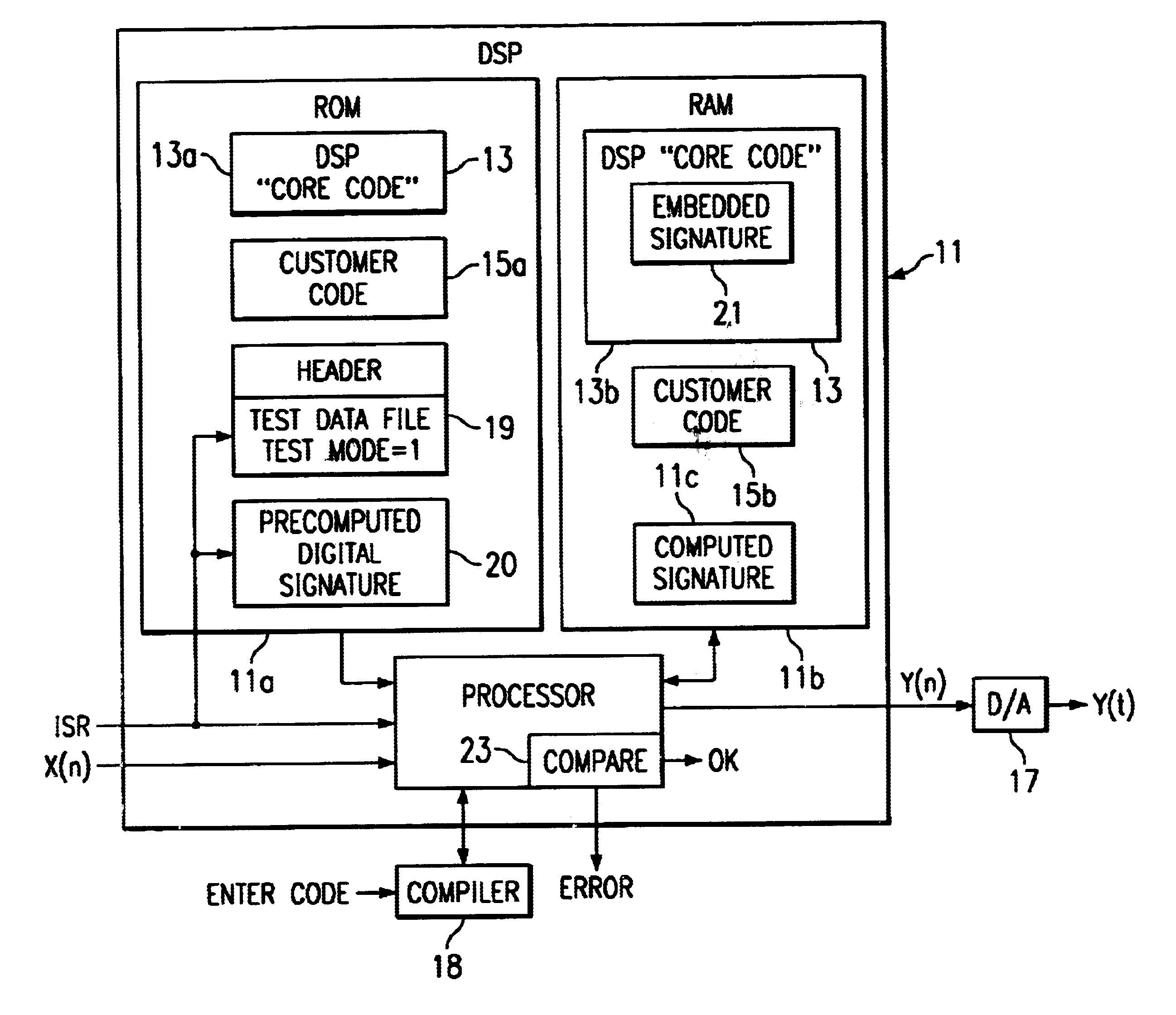
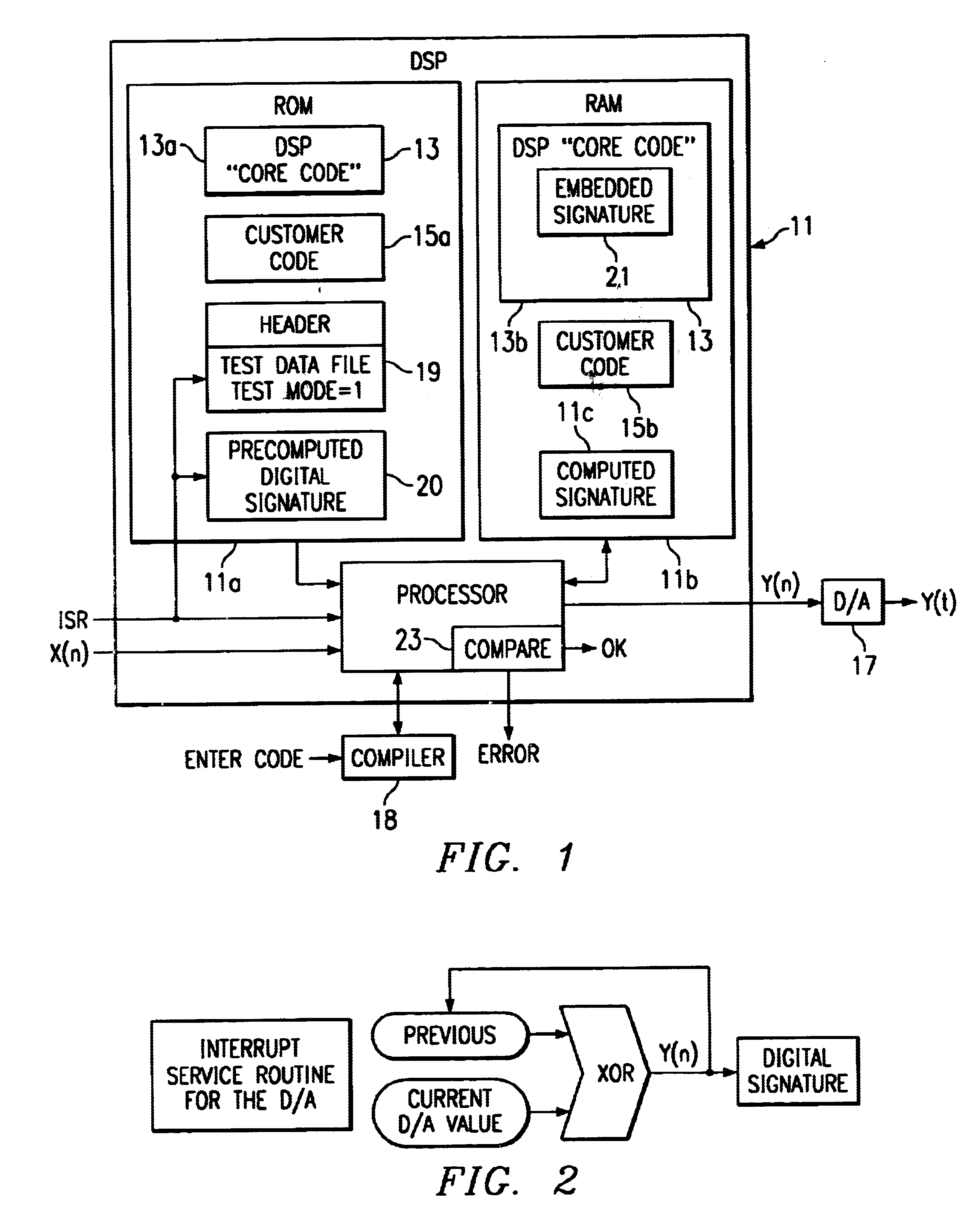
Referring to FIG. 1, the digital input signal X (n) is applied to the DSP 11 including the DSP "core" code 13 and the customer code (periphery code) 15. The digital output Y (n) signal is applied to a digital to analog D / A converter 17 to provide analog output Y (t). The DSP includes a Read Only Memory (ROM) 11a and Random Access Memory (RAM) 11b. The DSP is provided to a customer with the DSP "core" code 13. Some of the core code 13a is stored in the ROM and some of the "core" variables 13b are stored in the RAM which could be written over by the customer. The customer adds his or her code (customer code)and compiles the code with compiler 18 into machine language to operate on the DSP. The user then determines if there are any bugs in the program and, if so, does any correction. The customer would then store some code in the ROM 11a at 15a and the variables in RAM 11b at 15b. The customer may write over part of the "core" variables in the section 13b of RAM 11b causing the system ...


PUM


Abstract

A method of testing the performance of real time DSP algorithms after customer code has been added and includes the steps of embedding a signature equation in the DSP code that calculates to a given signature value at the output of the DSP when running a test mode program through the DSP.

Description

This invention relates to Digital Signal Processors (DSP), and more particularly to testing of the performance of real time DSP algorithms.BACKGROUND OF INVENTIONDSPs are used in many applications including use in modems, cellular phones, motor controls, and toys.Subtle interactions between customer (known as peripheral) code and DSP algorithms can cause the digital output signal to deviate from the desired signals leading to performance degradation, customer returns, etc.Multiple tests are needed to check if the digital signal has been corrupted. These tests require significant effort to establish and are time consuming. Some of these tests have to be done "offline" by taking the DSP out of it's application.SUMMARY OF INVENTIONIn accordance with one embodiment of the present invention, a digital signature equation is embedded in a processor code and when the processor is operated real time, the resultant signature output is used to verify if the processor has been corrupted.IN THE ...

Claims


Application Information

Patent Timeline
IPC IPC(8): G06F11/277G06F11/267G06F11/273
CPCG06F11/2236G06F11/2635G06F11/277
Inventor NARAYAN, SUMANRAO, TANDHONI S.
Owner TEXAS INSTR INC
Why Eureka
Try Eureka