
Engagement and disengagement mechanism for a coaxial starter motor assembly

a technology of coaxial starter motor and disengagement mechanism, which is applied in the direction of engine starter, machine/engine, electric generator control, etc., can solve the problems of more expensive starter motor assembly and need for a larger solenoid

Inactive Publication Date: 2003-10-14
BORGWARNER INC
View PDF117 Cites 36 Cited by
  • Summary
  • Abstract
  • Description
  • Claims
  • Application Information

AI Technical Summary

Problems solved by technology

The axial thrust force pulls the pinion into engagement with the ring gear when a cranking torque is applied and tends to push the pinion out of mesh from the ring gear when the engine starts due to overrunning torque.
To achieve such a high spring force, the spring would have to be large, which would result in the need for a larger solenoid.
Both a larger spring and a larger solenoid would result in a more expensive starter motor assembly.

Method used


Image

  • Engagement and disengagement mechanism for a coaxial starter motor assembly
  • Engagement and disengagement mechanism for a coaxial starter motor assembly
  • Engagement and disengagement mechanism for a coaxial starter motor assembly

Examples


example

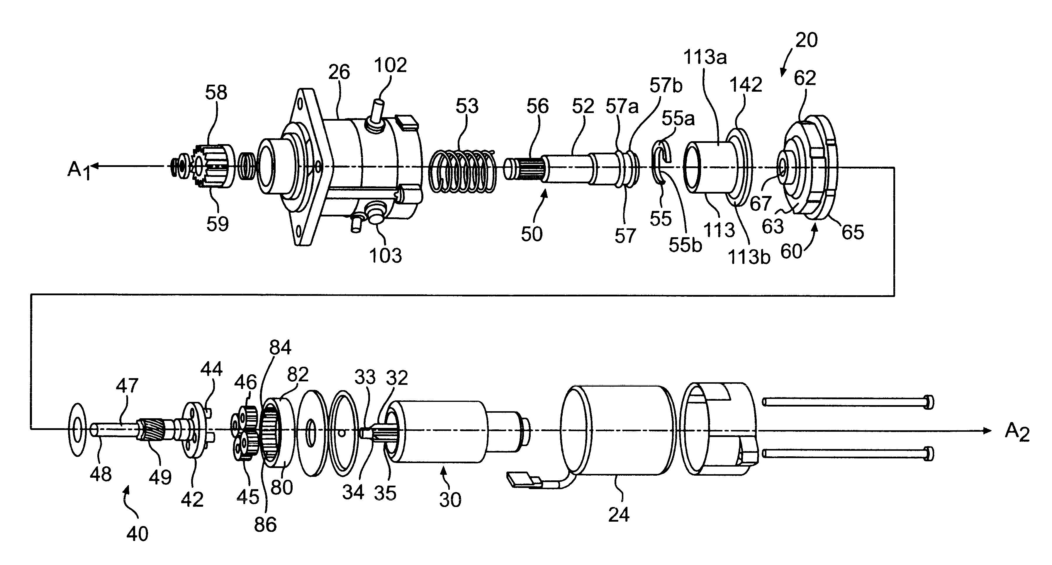
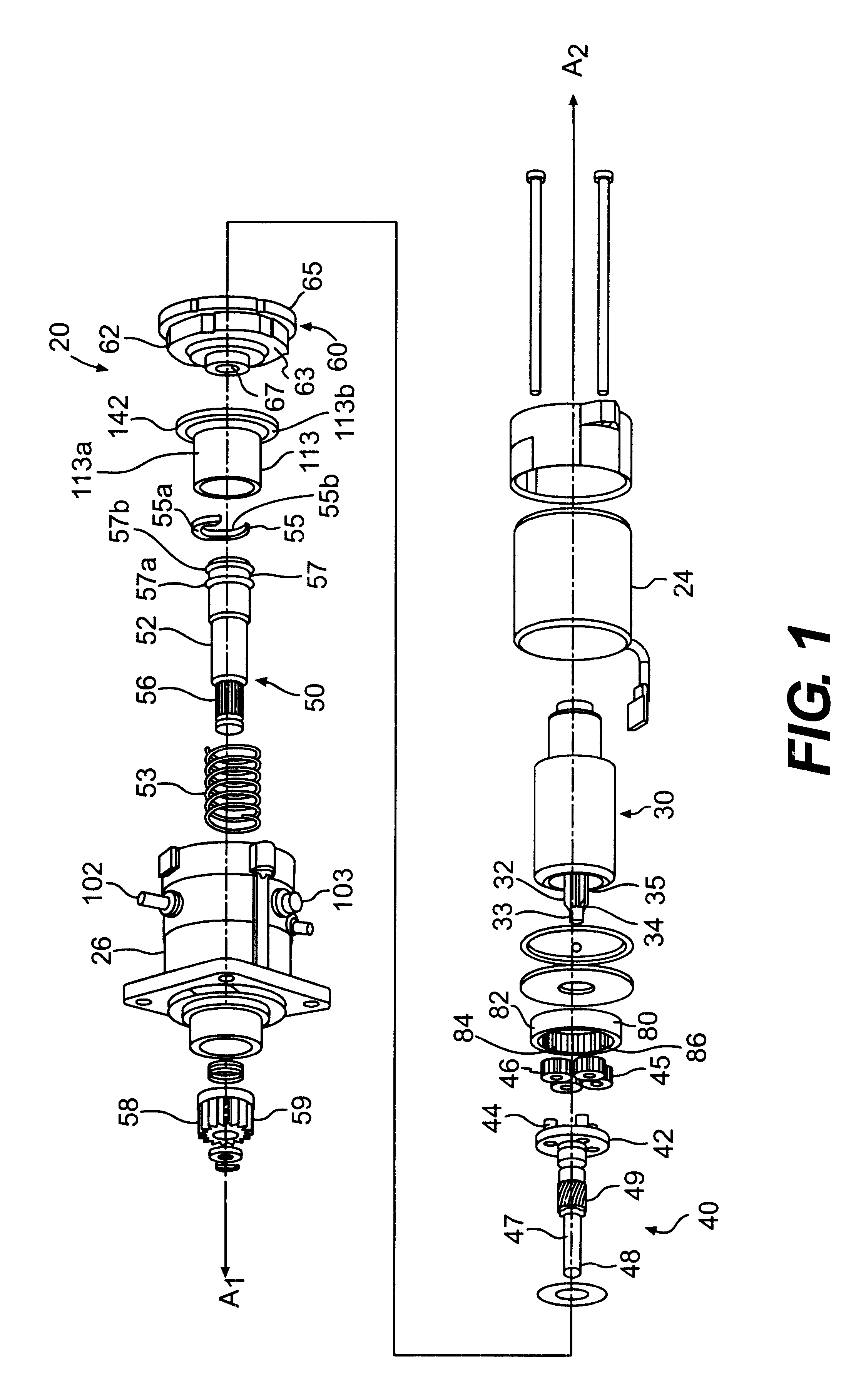
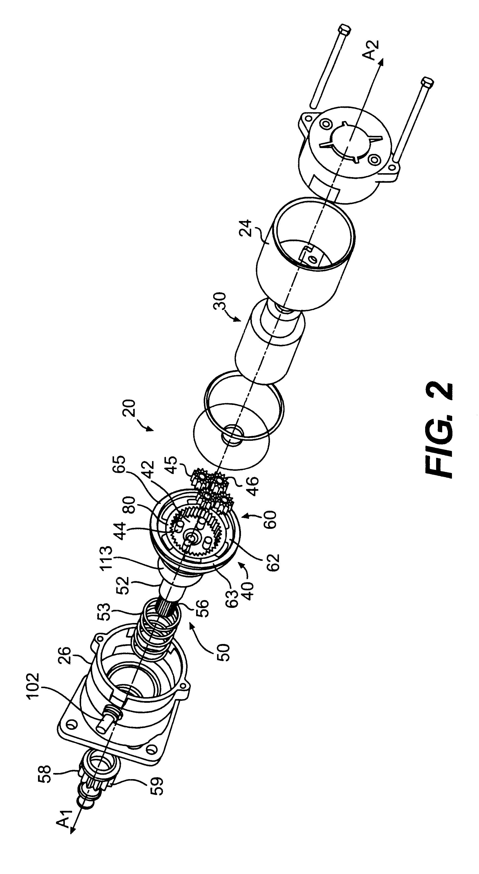
The following is an example of designing a starter motor assembly to minimize the distance that the solenoid plunger 113 travels ("the plunger stroke") using the equations and distances discussed above. In this example, the following distances are first determined from experience or known tolerances:

(1) D=19 millimeters (mm);

(2) G.sub.min =2 mm;

(3) H.sub.min =1 mm; and

(4) K.sub.min =1 mm.

Using equation number 1 above, the distance B may be calculated. In particular, with K.sub.min =1 mm, D=19 mm, and B=K.sub.min +D, the distance B is 1 mm+19 mm=20 mm.

Then, substituting B=20 mm into equation number 3 above, the distance C may be calculated. In particular, with G.sub.min =2 mm, B=20 mm, and C=G.sub.min +B, the distance C is 2 mm+20 mm=22 mm.

Then, substituting D=19 mm and C=22 mm into equation number 2 above, the distance A may be calculated. In particular, with H.sub.min =1 mm, D=19 mm, C=22 mm, and A=H.sub.min -D+C, the distance A=1 mm-19 mm+22 mm=4 mm.

Thus, using the known distances...


PUM


Abstract

A coaxial starter motor assembly that includes a housing. An electrical motor is provided in the housing that has a rotatable armature shaft that is linked with a drive shaft. A pinion assembly is provided that is engageable at one end with the drive shaft and includes a pinion at the other end engageable with a flywheel of an engine. A solenoid assembly is provided for selectively energizing the electrical motor. The solenoid assembly is coaxial with the drive shaft. The solenoid assembly includes a plunger having a bore. The plunger is engageable with the pinion assembly to move the pinion assembly including the pinion into engagement with the flywheel. The plunger is also engageable with a moveable contact to move the moveable contact to electrically connect with a pair of fixed contacts. A return spring is provided that is positioned at least in part within the bore of the plunger of the solenoid assembly for moving the pinion assembly including the pinion away from engagement with the flywheel. The return spring is spaced from the pinion assembly. Energization of the solenoid assembly moves the plunger to move the pinion assembly to engage the pinion with the flywheel. Upon deenergization of the solenoid assembly, the plunger is capable of moving independently of the pinion assembly to thereby break the electrical connection between the moveable contact and the fixed contacts before the return spring moves the pinion assembly to move the pinion away from engagement with the flywheel.< / PTEXT>

Description

DESCRIPTION OF THE INVENTION1. Field of the InventionThe invention relates to a starter motor assembly for starting an engine and, more particularly, to an engagement and disengagement mechanism for a coaxial starter motor assembly. This application is being filed concurrently with U.S. patent application Ser. No. 10 / 002,167, entitled Coaxial Starter Motor Assembly Having a Return Spring Spaced From the Pinion Shaft, with inventors David A. Fulton and James D. Stuber, and assigned to Delco Remy America, Inc.2. Background of the InventionStarter motor assemblies to assist in starting engines, such as engines in vehicles, are well known. The conventional starter motor assembly broadly includes an electrical motor and a drive mechanism, which generally includes a mechanism for engaging and disengaging a pinion-type gear with an engine flywheel. The electrical motor is energized by a battery upon the closing of an ignition switch. The drive mechanism transmits the torque of the electric...

Claims


Application Information

Patent Timeline
Patent Type & Authority Patents(United States)
IPC IPC(8): H02K7/10H02K7/108H02K7/116
CPCH02K7/1085H02K7/116Y10T74/132
Inventor FULTON, DAVID A.STUBER, JAMES D.
Owner BORGWARNER INC
Learn More