Braided optical fiber bundles

a bundle and fiber technology, applied in the direction of fibre light guides, lighting and heating apparatus, instruments, etc., can solve the problems of prior art patents that do not teach the braiding of optical fibers to form fiber optic light-emitting panels

Inactive Publication Date: 2003-10-21
BELFER BRUCE D
View PDF3 Cites 36 Cited by
  • Summary
  • Abstract
  • Description
  • Claims
  • Application Information

AI Technical Summary

Problems solved by technology

This prior art patent does not teach the braiding of optical fibers to form a fiber optic light-emitting panel.
This prior art patent does not teach the use of phosphorous-coated cladding of the braided optical fibers to produce a brighter light with a glowing effect within the fiber optic light-emitting panel.
None of the prior art patents teach or disclose the braiding of optical fibers within a fiber optical bundle or forming the bundle into a sheet for the purpose of emitting more light or leaking more light from a fiber optic light-emitting panel as compared to woven or twisted optical fiber bundles.
In addition, none of the prior art patents teach or disclose the use of phosphor(ous)-coated cladding of the braided optical fibers to produce a brighter light with a glowing effect when the light is leaked along the path of the braided optical fibers within the bundle.

Method used


Image

  • Braided optical fiber bundles
  • Braided optical fiber bundles
  • Braided optical fiber bundles

Examples


Embodiment Construction

Overview

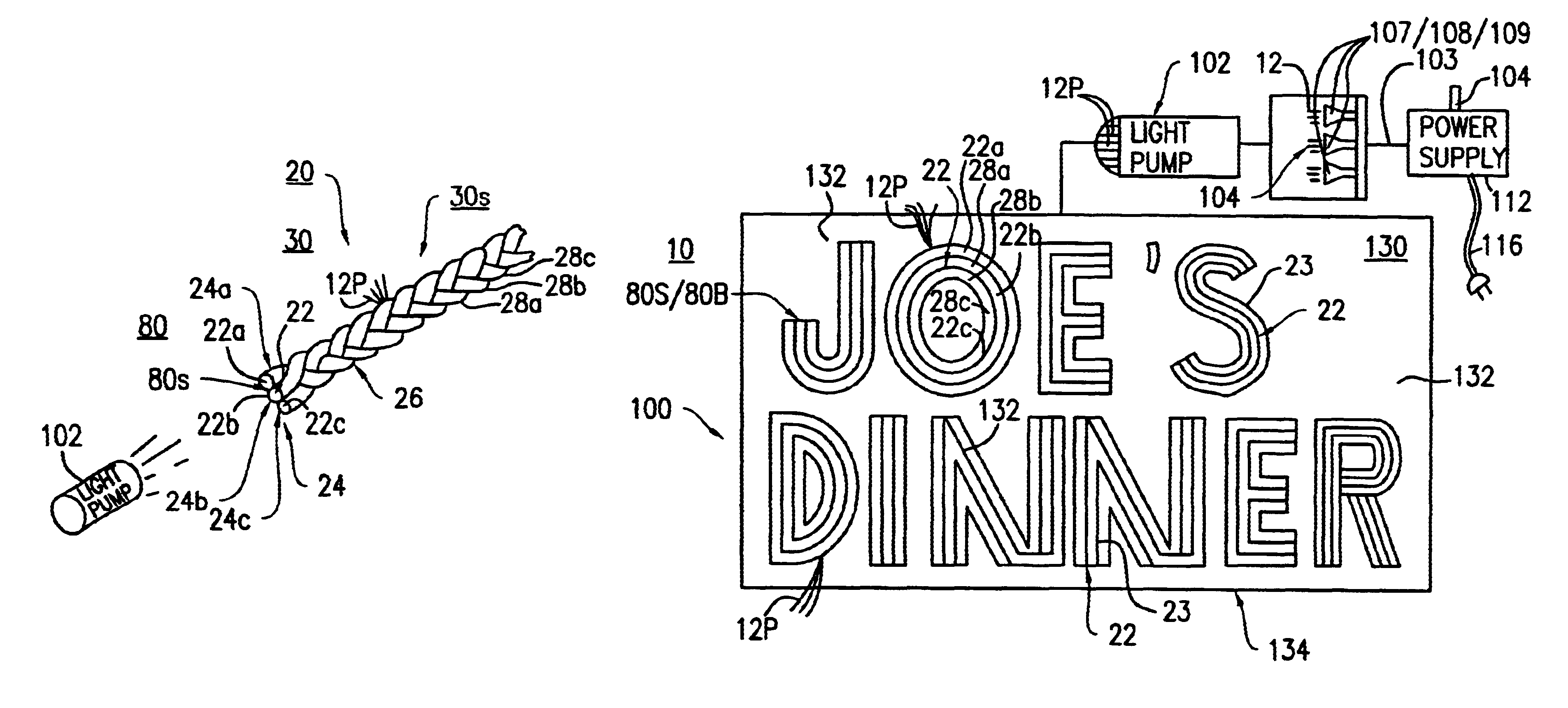
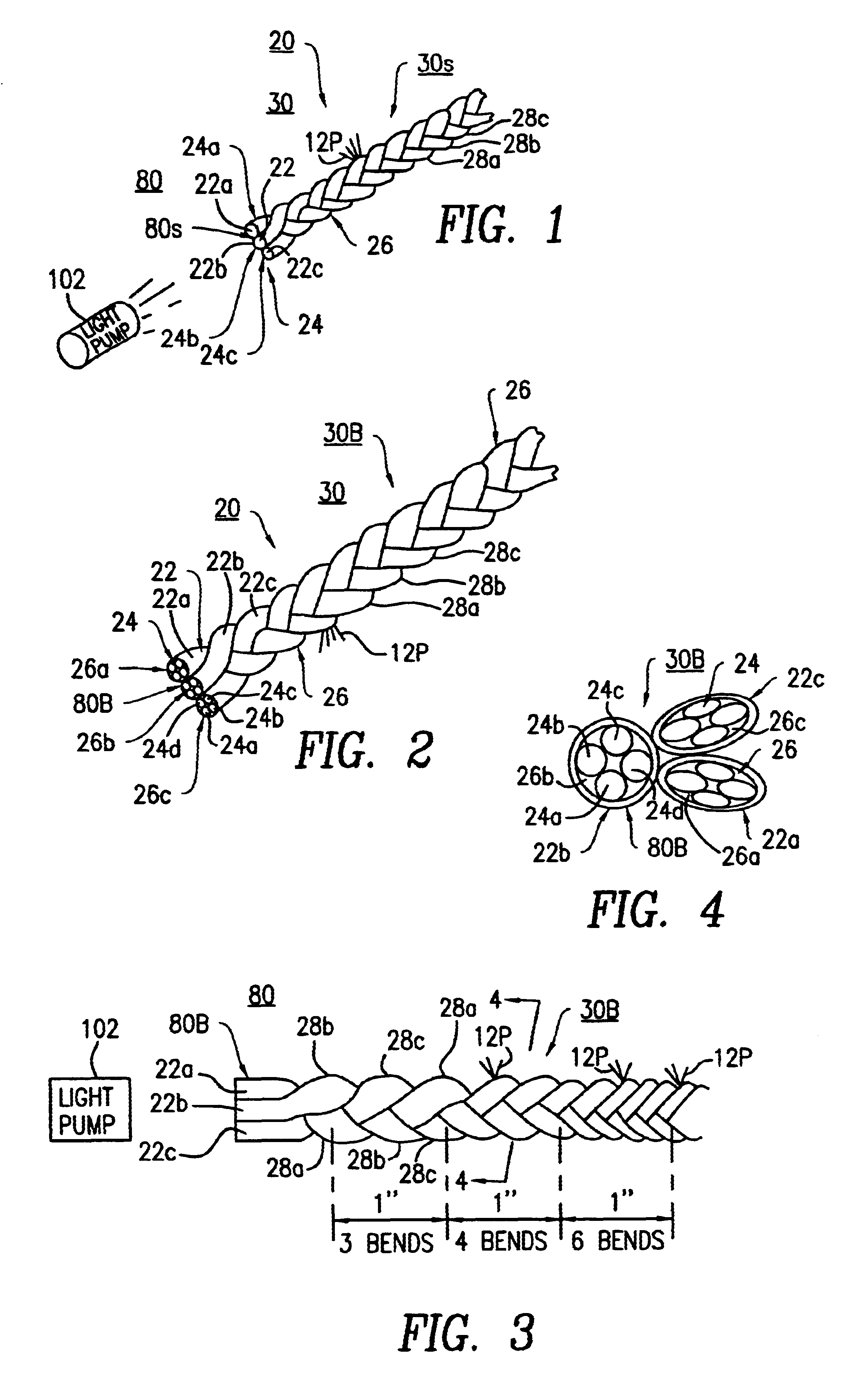
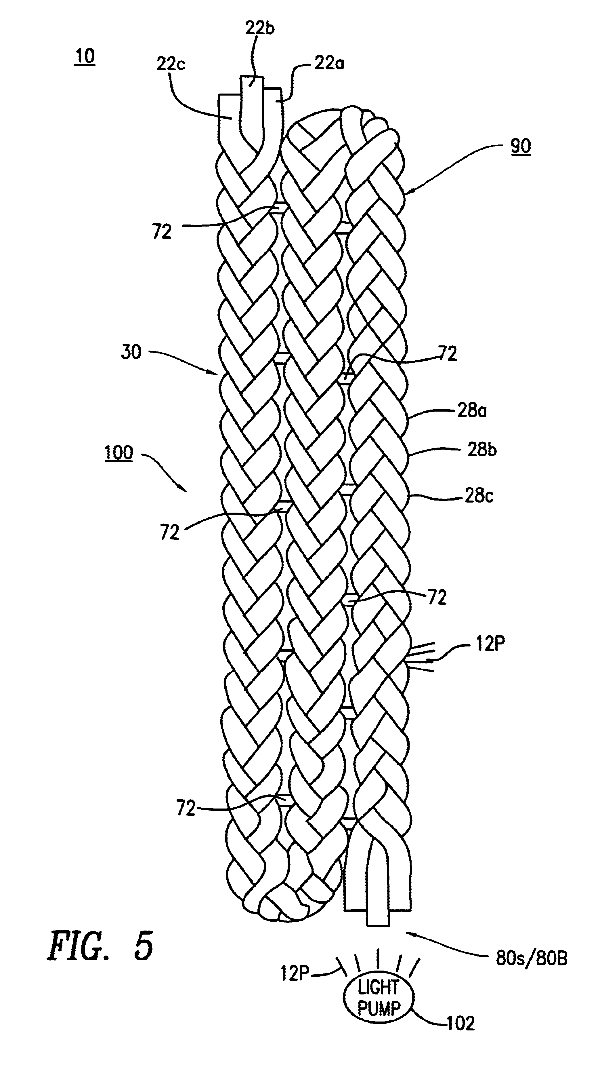
The fiber optic light-emitting panel 10, having braided structures 30, 40, 50 or 60 therein, of the preferred and alternate embodiments of the present invention are represented in detail by FIGS. 1 through 16 of the drawings. The fiber optic light-emitting panel 10 of the preferred embodiment, as shown in FIGS. 1 through 6 of the drawings, includes a plurality of braided fiber optic strand assemblies 80S or 80B having a triple braid configuration 30S or 30B therein, using various forms of connection means 70 for forming a light-transmitting device 100. An example of a light-transmitting device 100 is a road-sign lighting fixture 120, as shown in FIG. 13 of the drawings.

Braided fiber optic strand assemblies 82S or 82B having a quadruple braid configuration 40S or 40B therein, respectively, as shown in FIGS. 7 and 8, include the braiding of four (4) strands 22 having optical fibers 24. Braided fiber optic strand assemblies 84S or 84B having a quintuple braid configuration 50S ...


PUM

PropertyMeasurementUnit
lengthaaaaaaaaaa
luminescent lightingaaaaaaaaaa
total internal reflectionaaaaaaaaaa

Abstract

A fiber optic light-emitting panel having one or more braided fiber optic strand assemblies formed into a light-transmitting device. The fiber optic light-emitting panel includes a plurality of three or more fiber optic strands braided together to form a braided fiber optic strand assembly. Each of the fiber optic strands includes a single optical fiber or a plurality of optical fibers to form a bundle. Each of the fiber optic strands within the braided fiber optic strand assembly has at least three (3) bends per inch along the length thereof for transmitting light laterally at the bends to form the light-transmitting device. The fiber optic light-emitting panel includes plastic ties for connecting at least two (2) of the braided fiber optic strand assemblies to form the fiber optic light-emitting panel. The fiber optic light-emitting panel further includes a light pump having a light source for applying an optical light signal to the braided strand assemblies for transmitting light from the bends of the fiber optic light-emitting panel.

Description

The present invention relates to a fiber optic light-emitting panel having braided optical fiber bundles formed into a sheet. More particularly, the fiber optic light-emitting panel is made luminous by bending the optical fibers along their length within the braided optical fiber bundles such that more light is emitted at the bends. In addition, braiding of the fibers produces more emitted radiant light along their length within the panel than weaving or twisting of the optical fiber bundles.In the prior art it is known to weave optical fibers and form a light-emitting panel to make the panel luminous in one or more selected areas by nullifying the total internal reflection characteristics of the optical fibers in such areas. Illumination in these selected areas is caused by allowing light which is transmitted to the woven optical fibers through a cable from a remote light source to emerge from the optical fibers in these selected areas.There is a limit to the amount of light that c...

Claims


Application Information

Patent Timeline
Patent Type & Authority Patents(United States)
IPC IPC(8): F21V8/00G02B6/04G02B6/00
CPCG02B6/0003G02B6/001G02B6/04G02B6/0083G02B6/006
Inventor BELFER, BRUCE D.
Owner BELFER BRUCE D
Why Eureka
Try Eureka