Load detection structure for vehicle seat

a technology for vehicle seats and loading devices, applied in the direction of instruments, force/torque/work measurement apparatuses, tractors, etc., can solve the problems of seat size increase, seat vertical size, and prior art is neither realistic nor practical in assembling optimal mechanical structures

Inactive Publication Date: 2003-11-04
TACHI S CO LTD
View PDF12 Cites 12 Cited by
  • Summary
  • Abstract
  • Description
  • Claims
  • Application Information

AI Technical Summary

Benefits of technology

Accordingly, there is eliminated the need to provide a great number of intricate parts and fittings for assembling the load detection structure in the seat as found in the prior art. It is therefore quite easy for a worker to assemble the seat with such load detection structure at highly reduced costs, and also, the worker can quickly secure the thus-assembled seat to the vehicle floor. The two flanged collars can easily be fitted in the respective two bearing holes and stably set therein temporarily, which makes it extremely easy for the worker to insert the pivot pin through both of the two holes and, thereby expediting the process for assembling a seat. For, this is indeed superior to the troublesome steps of interposing cylindrical spacers between the block member and support leg member while simultaneously inserting the pivot pin through all the bores and spacers. The flanged collars are also effective in preventing the block member against transversal dislocation with respect to the support leg means, thus contributing to a high sensitivity of the strain gauge to the vertically applied load or force.

Problems solved by technology

However, the Japanese Laid-Open Patent Publication No. 11-001153 has no description regarding the mechanical structure of load sensor itself, and has no specific teaching on how the load sensor structurally supports the seat and how it actions to detect the seat occupant's weight.
This prior art is therefore neither realistic nor practical in assembling an optimal mechanical structure between the sensor and seat.
The Japanese Laid-Open Patent Publication No. 11-304579 is found defective in that its link mechanism and pivoted arm are complicated in structure and further they occupy much of space heightwise between the seat and slide rail device, which results in the seat becoming large vertically in size and increasing its weight.
Also, no particular design has been contemplated to make assembling the load detection system easy and to render the structure of load detection system adaptable for mounting on the shape and condition of floor of vehicle.

Method used


Image

  • Load detection structure for vehicle seat
  • Load detection structure for vehicle seat
  • Load detection structure for vehicle seat

Examples


Embodiment Construction

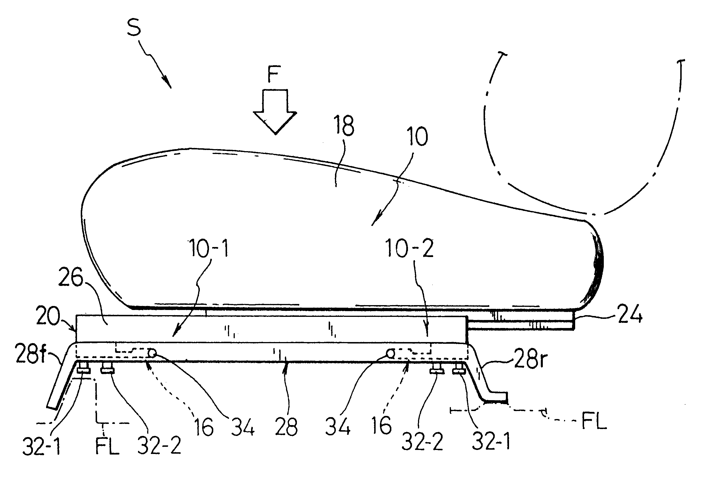
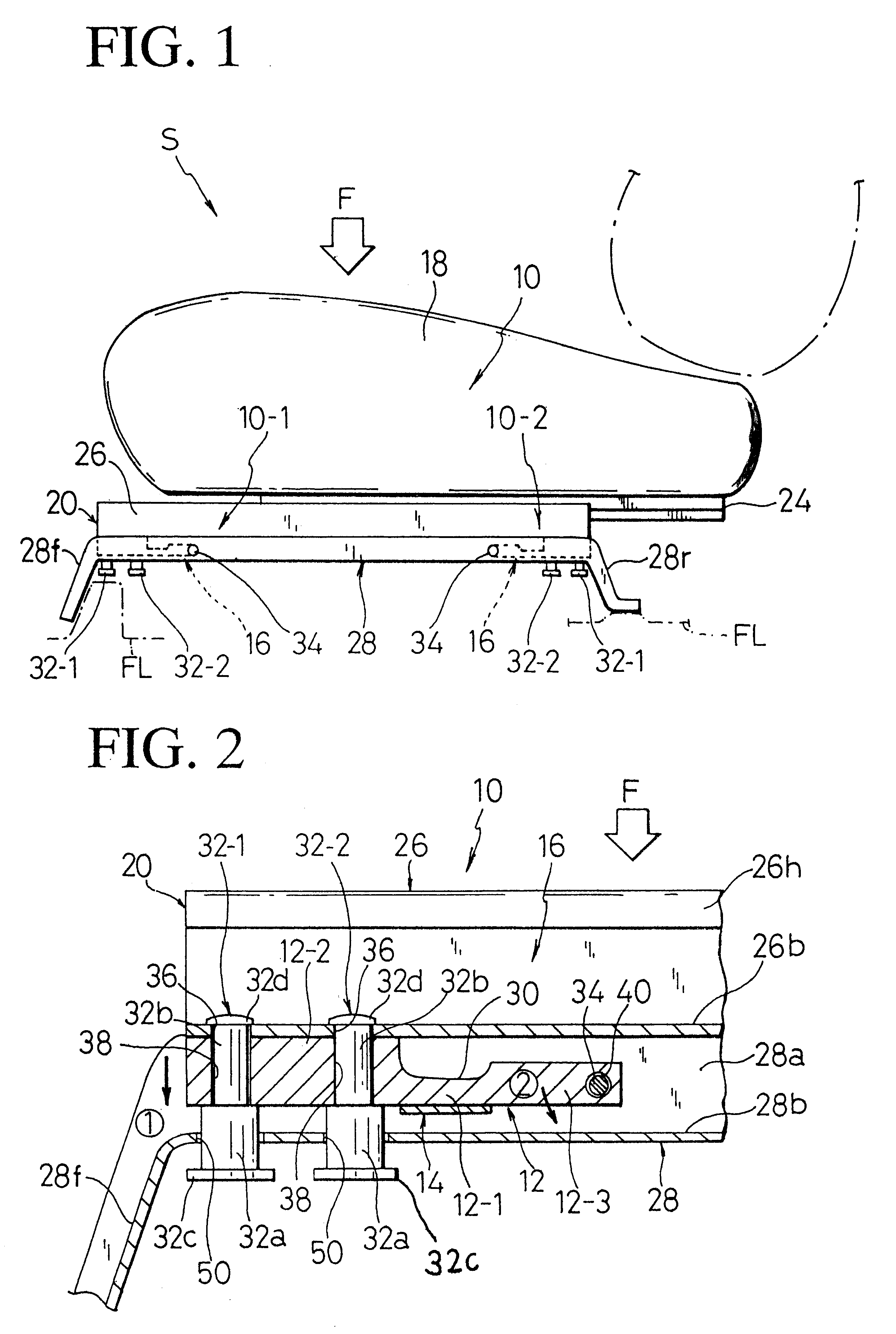
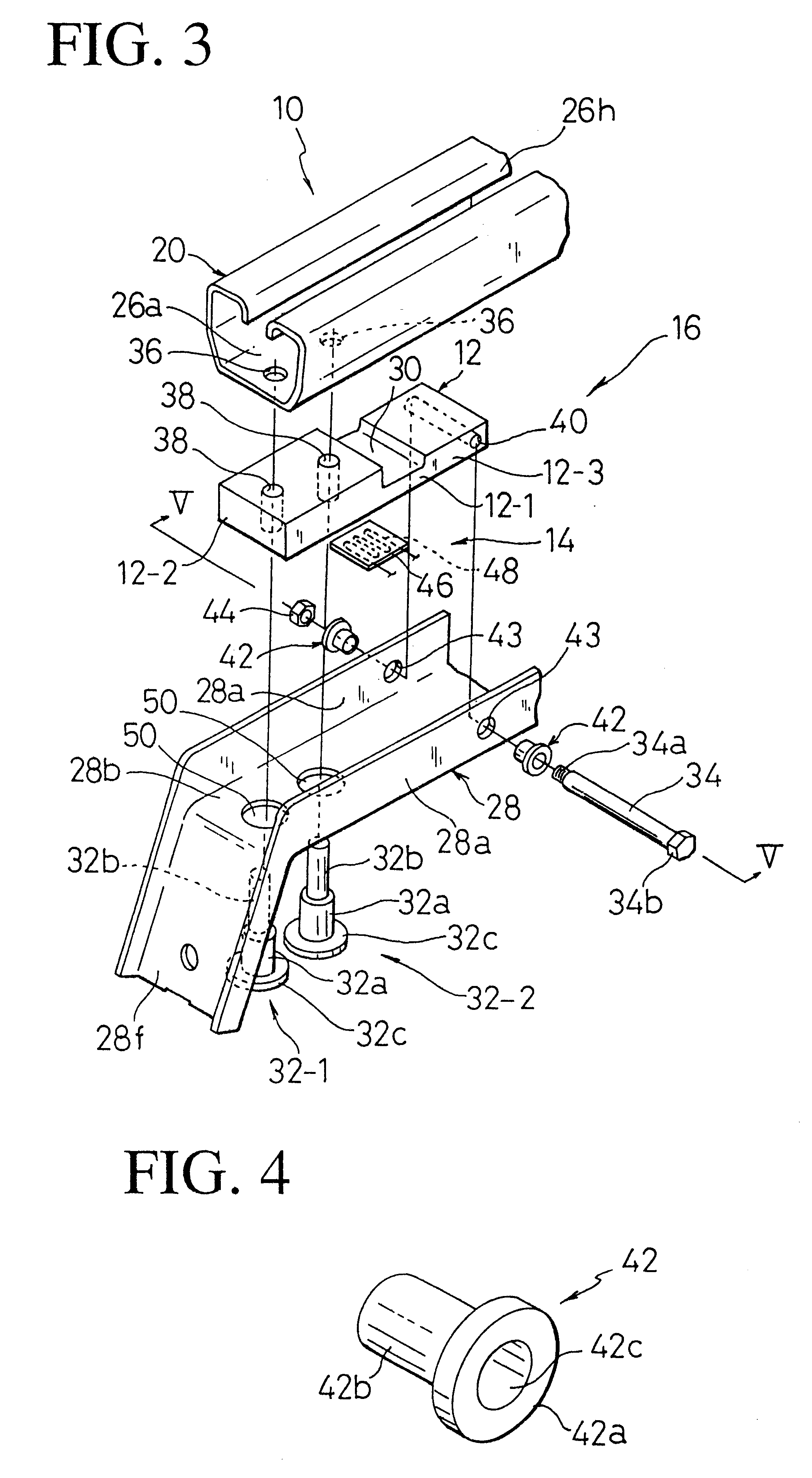
Referring to FIGS. 1 through 6, there is illustrated one preferred mode of load detection structure applicable to a vehicle seat in accordance with the present invention. Reference is first made to FIG. 1 in which designation (10) generally represents a load detection structure provided between a slide rail device (20) and a support leg member (28) in a novel simplified manner.

As is known, the slide rail device (20) comprises a stationary lower rail (26) to be fixed on a floor (FL) of a vehicle (not shown) and a movable upper rail (24) slidably fitted in and along the longitudinal slit (26h) of the lower rail (26). The typical configuration of such slide rail device (20) is shown in the figures, wherein the movable upper rail (24) has generally inverted-T-shaped base portion slidably accommodated within the lower rail (26) via steel balls and rollers (not shown). As seen from FIG. 1, the upper rail (24) is fixedly attached to a seat cushion (18) of a vehicle seat (S) whereas the low...


PUM

PropertyMeasurementUnit
diameteraaaaaaaaaa
weightaaaaaaaaaa
total weightaaaaaaaaaa

Abstract

A load detection structure in a vehicle seat with a support leg member, which includes a rigid yet resilient block member having a pivotal end portion, a thin intermediate portion, and a securing portion in which pin (s) is / are provided, and a strain gauge attached to the thin intermediate portion of block member. The support leg member has at least one first hole formed in the bottom wall thereof and two second holes formed in the respective two vertical walls thereof. The block member is arranged between the seat and support leg member, such that the securing portion thereof of is fixed via one end of the pin (s) to the seat, with another end of the pin (s) extending through the at least one first hole, while the pivotal end portion of block member is rotatably connected with the support leg member by fitting two flanged collars in the two second holes, respectively, and then inserting a pivot pin through those two flanged collars and second holes.

Description

BACKGROUND OF INVENTION1. Field of the InventionThe present invention relates to a structure allowing for detection of a load applied to a vehicle seat. In particular, the invention is directed to such load detection structure for use in a vehicle seat.2. Description of Prior ArtRecent years have witnessed a tendency for various automatically controlled functions and mechanisms to be increasingly incorporated in vehicle or automobiles, including safety devices such as air bags for protecting passengers against a great impact automatically in response to a collision, as well as various kinds of seat position adjustment devices for automatically adjusting the positions of seat sensitive to driver's or passenger's physiques and seating conditions. With such automated control innovations, there have been also found technical improvements to a passenger detection system for detecting the presence and absence of a passenger or driver in a seat of vehicle in advance before actuating or sto...

Claims


Application Information

Patent Timeline
Patent Type & Authority Patents(United States)
IPC IPC(8): B60R21/01G01G19/40G01G19/414B60R21/015
CPCG01G19/4142B60R21/0152B60R21/01516
Inventor ISHIDA, TOSHIAKI
Owner TACHI S CO LTD
Why Eureka
Try Eureka