Binding device for a big baler

a technology of a binding device and a baler, which is applied in the field of binding devices for balers, can solve the problems of twine loosening and the loss of the compressed density of the formed bale, and achieve the effect of simple means of controlling operation

Inactive Publication Date: 2003-11-11
LELY VERMEER MASCHFAB
View PDF14 Cites 5 Cited by
  • Summary
  • Abstract
  • Description
  • Claims
  • Application Information

AI Technical Summary

Benefits of technology

According to the present invention, the engagement of the knotter shaft takes place, in the power flow direction, after the one-stop clutch. As a result, the one-stop clutch can be driven with a transmission ratio of 1:1 with respect to the crank drive of the plunger, without a need in additional control means for controlling the operation of the one-stop clutch. The actuation of the one-stop clutch is controlled by a measurement wheel, which determines or detects the length of the formed bale, independent from the plunger operation, as in the conventional balers. Therefore, the start of the rotation of the knotter shaft need not be changed in comparison with conventional balers, but the twine needle moves in and out of the baling channel with a greater speed. The transmission ratio determines the speed of the twine needle movement in and out of the baling channel and can be varied. Thus, according to the selected transmission ratio, the binding can start after the plunger dead point or in the dead point. However, the further away from the dead point the binding starts, the greater would be the twine loosening and the loss of the compressed density of the formed bale.
Further advantages of the present invention consists in that: The twine needle leaves the baling channel earlier and, as a result, danger of the needle being damaged during a following compression stroke of the plunger is eliminated; The bale shape and its compression density are improved, as no or smaller twine loosening takes place; The twine needle / plunger adjustment can be more reliably selected because the plunger has a greater overrun with respect to the twine needle; Use of larger adjustment tolerances becomes possible; and The inventive design requires use of only small number of additional components, with other components remaining the same as in the conventional constructions.
The present invention expands the variation possibilities of the controlling operation of the binding device without electronic measurement of the bale length and actuation of the one-stop clutch.
To reduce the weight of the device, at least some of the components of the needle drive, the one-stop clutch and the transmission means, are formed of a light metal.

Problems solved by technology

However, the further away from the dead point the binding starts, the greater would be the twine loosening and the loss of the compressed density of the formed bale.

Method used


Image

  • Binding device for a big baler
  • Binding device for a big baler
  • Binding device for a big baler

Examples


Embodiment Construction

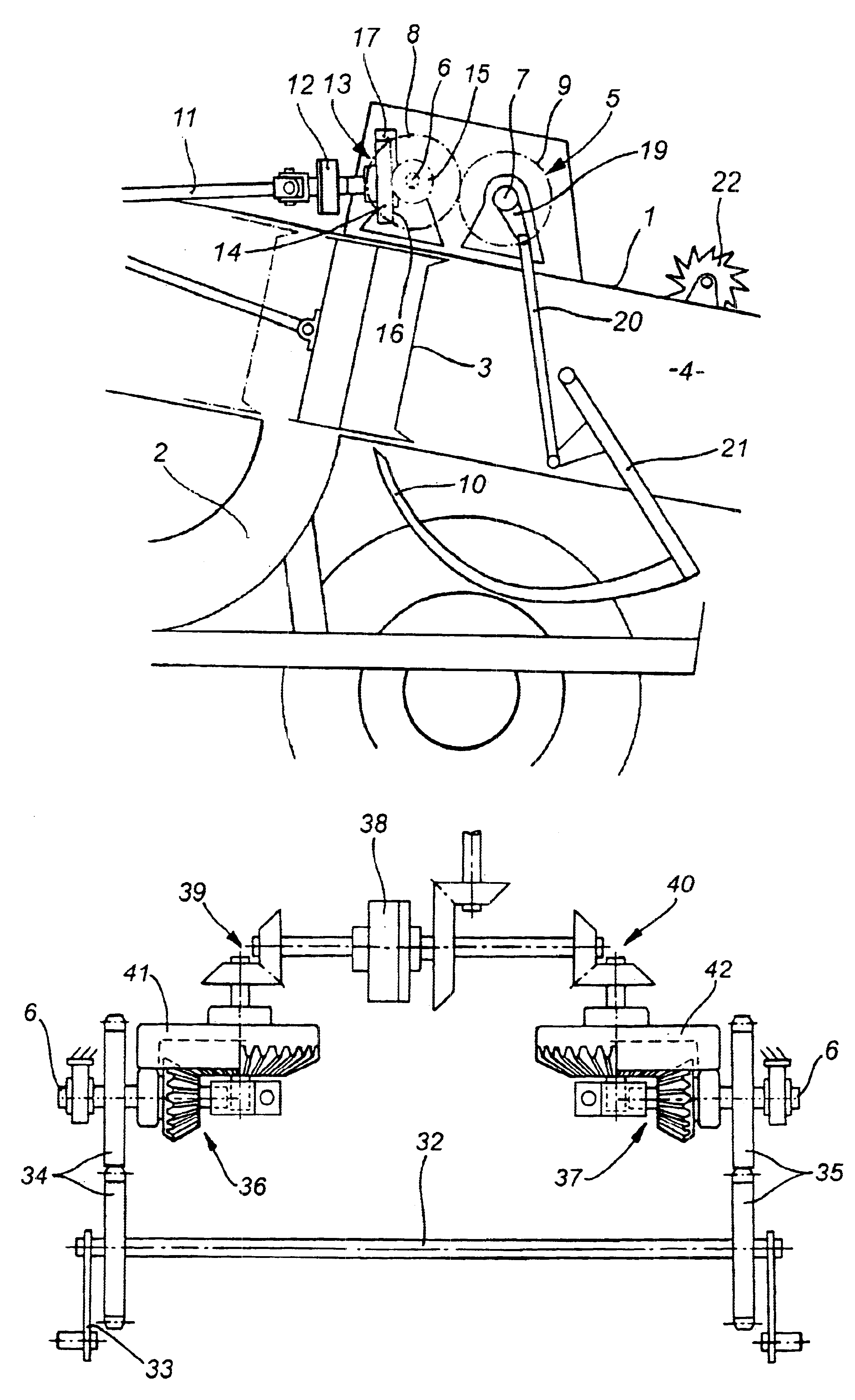
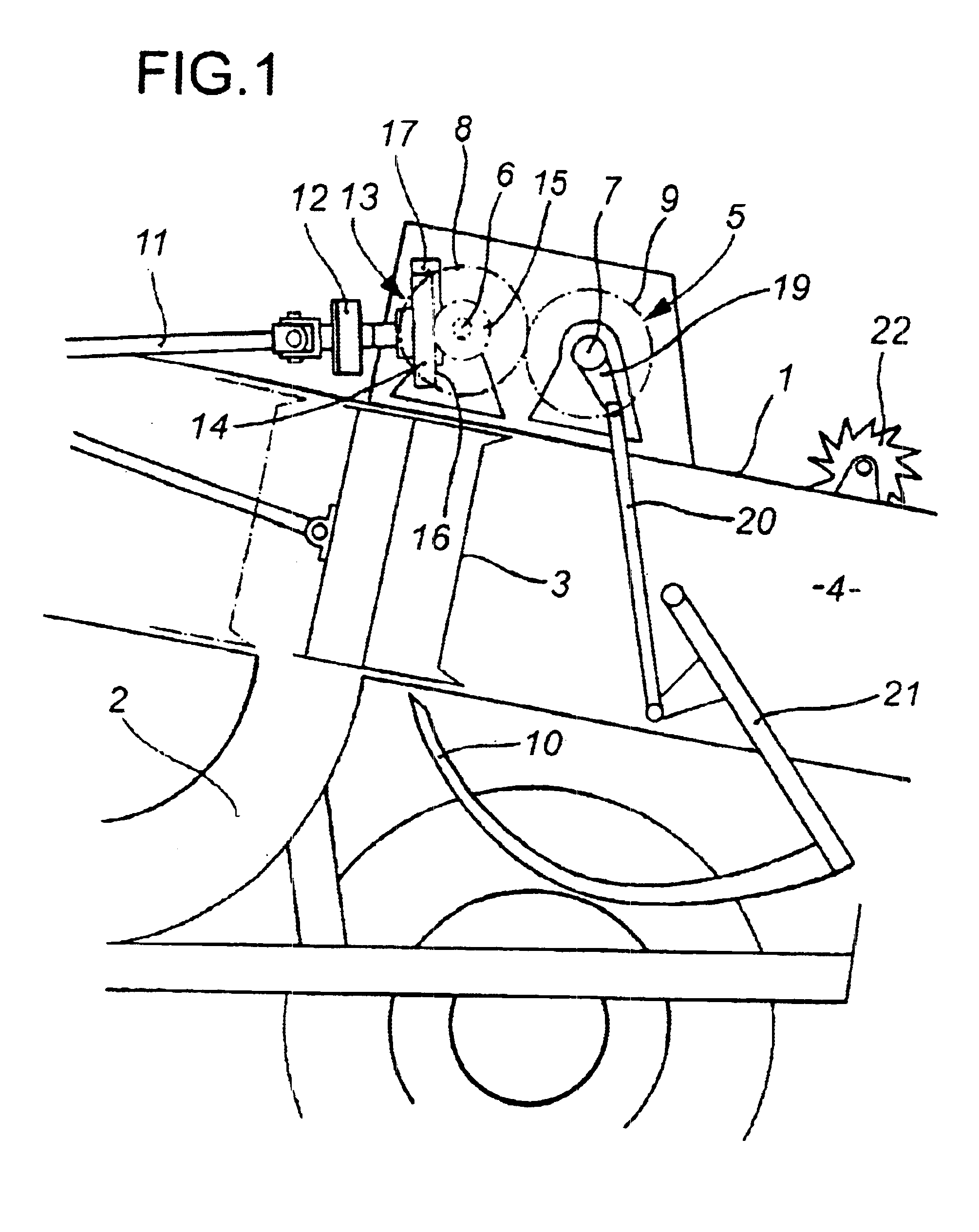
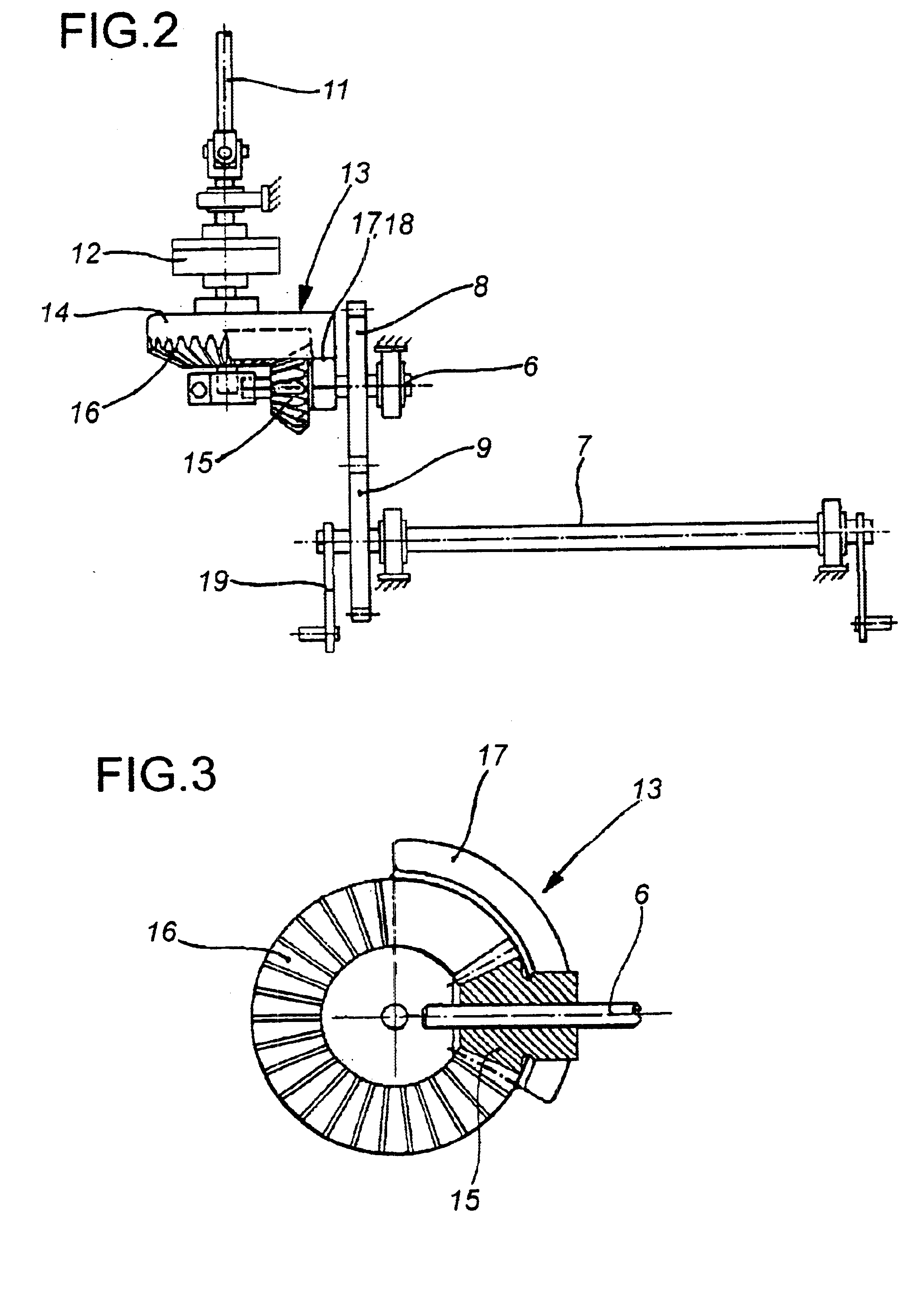
A big baler 1, which is shown partially in FIG. 1, includes a delivery channel 2, a plunger 3, a baling channel 4, and a binding device 5. The baler 1 cooperates with a twine knotter (not shown) driven by a knotter shaft 7 that extends parallel to a connecting shaft 6 and is driven thereby. Respective spur gears 8, 9, which engage each other and have the same number of teeth, are fixedly secured on the connecting shaft 6 and the knotter shaft 7, respectively. The spur gears 8 and 9 provide for transmission of a rotational movement from the connecting shaft 6 to the knotter shaft 7. The knotter shaft 7 drives twine needles 10 and twine knotters (not shown) that cooperate with respective twine needles 10. The drive transmission is effected from a drive (not shown) by a drive shaft 11. The transmission ratio between the shaft 11 and the drive of the plunger 3 is 1:1. The drive shaft 11 is arranged perpendicular to the connecting shaft 6. A one-stop clutch 12 is mounted on the drive sha...


PUM


Abstract

A binding device for a baler including at least one twine needle, a knotter shaft for driving the needle, a one-stop clutch for connecting the knotter shaft with the plunger drive and for intermittently driving the knotter shaft, and a transmission unit provided between the one-stop clutch and the knotter shaft and including elements which insure that for one complete revolution of the one-stop clutch, the knotter shaft also performs one complete revolution but with a higher speed than the one-stop clutch.

Description

BACKGROUND OF THE INVENTION1. Field of the InventionThe present invention relates to a binding device for a baler including at least one knotter and a twine needle driven by the knotter shaft driven by the baler plunger drive, a one-stop clutch for connecting the knotter shaft with the plunger drive and for intermittently driving the knotter shaft, and transmission means provided between the one-stop clutch and the knotter shaft.2. Description of the Prior ArtSuch knotters are most often used in balers for forming bales of agricultural harvest goods, but they can also be used for forming bales from paper products, paperboards, recyclable products, and the like. Generally, a plurality of knotters are arranged next to each other over the baling channel. When a bale reaches a predetermined length, the knotter secures the bale with twine loops.All of the presently available on the market balers use a knotter the shaft of which is driven so that the drive ratio between the knotter shaft ...

Claims


Application Information

Patent Timeline
Patent Type & Authority Patents(United States)
IPC IPC(8): A01F15/08A01F15/00
CPCA01F15/0858A01F2015/0866
Inventor HONHOLD, JOOST
Owner LELY VERMEER MASCHFAB
Why Eureka
Try Eureka