Device for a space vessel

a technology for space vessels and devices, applied in the direction of cosmonautic components, rod connections, sheet joining, etc., can solve the problems of impact and/or shock waves in the parts of space vessels, and it is difficult to rectify any errors that may arise, so as to reduce the energy stored

Inactive Publication Date: 2003-11-18
SAAB ERICSON SPACE
View PDF7 Cites 16 Cited by
  • Summary
  • Abstract
  • Description
  • Claims
  • Application Information

AI Technical Summary

Benefits of technology

The radially active forces of the coupling are transferred to other parts of the space vessel by way of a weakened point in one of the parts of the space vessel on which the coupling is intended to act. A radial stop is arranged on the second space vessel part and is intended to transfer additional portions of the radial force from the coupling via a notch in the first flange on the first space vessel part to the second space vessel part. The weakened point thus decreases the energy stored in the first part and obtained from the force produced by the coupling. The attenuated part can thus bend aside and permit the second flange to absorb the force and thus store the bulk of the energy.

Problems solved by technology

These coupling devices must maintain low weight, and must be designed for extremely high reliability in view of the very high launching costs, while it is at the same time impossible to rectify any errors that may arise once the vessel has left the ground.
This results in the occurrence of an impact and / or shock wave in those parts of the space vessel on which the coupling had been acting.

Method used


Image

  • Device for a space vessel
  • Device for a space vessel

Examples


Embodiment Construction

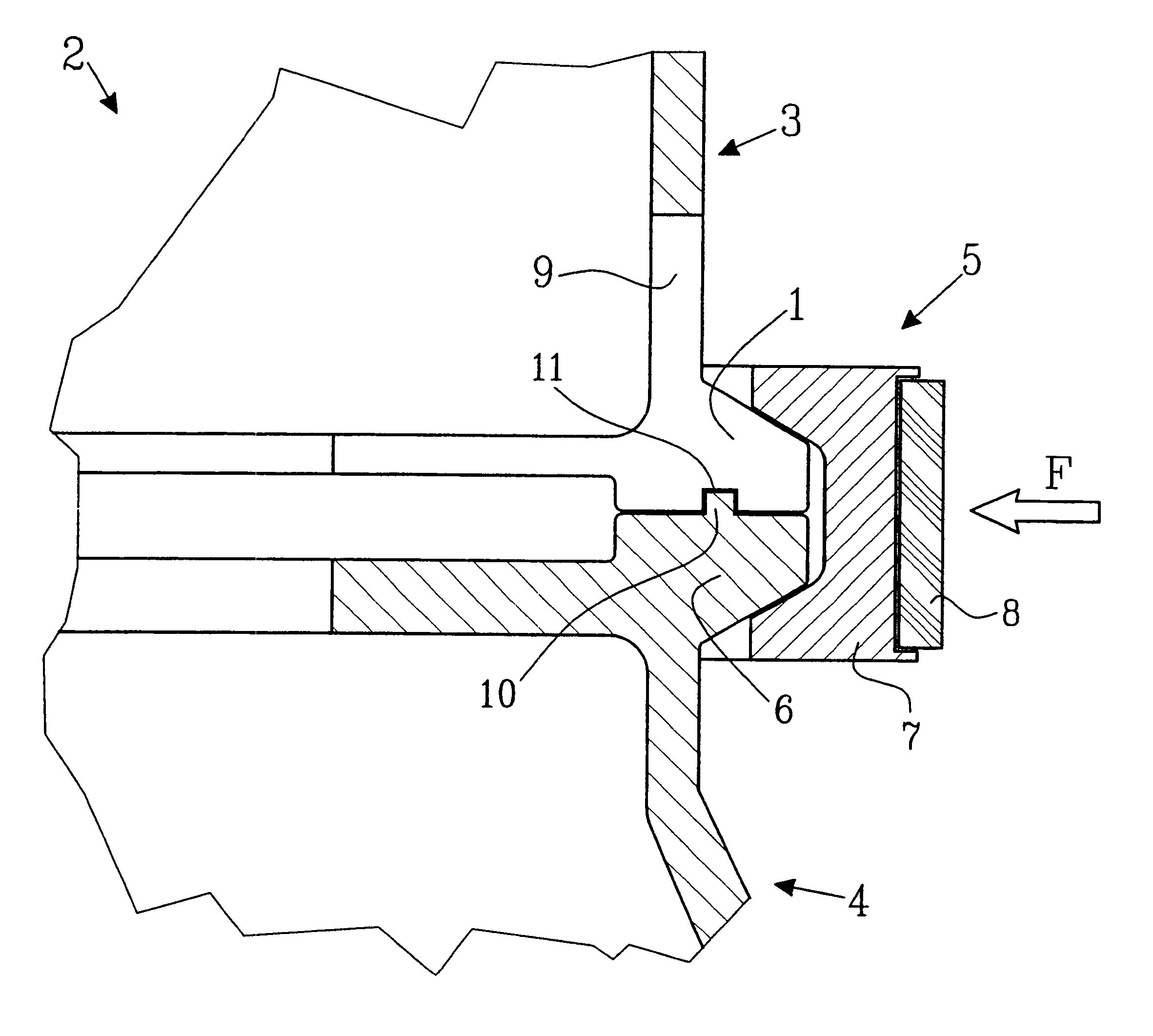
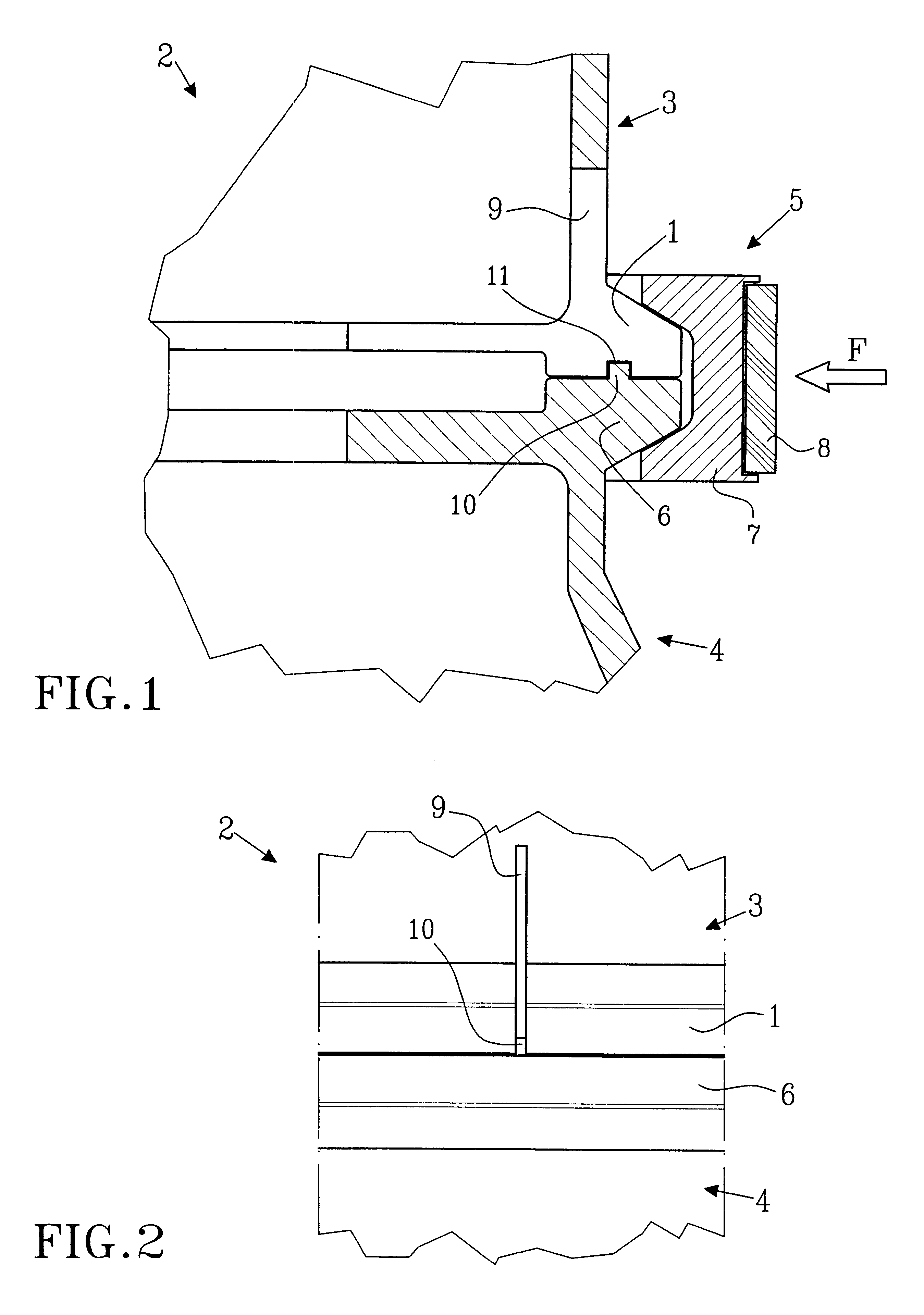
A first flange is designated in the drawing as 1, and a space vessel is designated as 2. The space vessel 2 includes two mutually separable parts 3, 4, e.g. a satellite part 3 placed on a booster rocket, 4, the "launcher part." A coupling 5 is arranged so as to hold the two parts 3, 4 together during that portion of the time in which the coupling 5 is in use.

The coupling 5 comprises the first flange 1 fixedly mounted on a lower portion of the first space vessel part 3 and a second flange 6 fixedly mounted on an upper portion of the second space vessel part 4. The coupling 5 further comprises one or more clips 7 distributed about the periphery of the flanges 1, 6 and a tensioning element 8 that runs around or through the clips 7 and pushes them radially inward against the flanges 1, 6. The clips 7 are thus arranged so as to convert a radial force from the tensioning element 8 into a clamping force and clamp the flanges 1, 6 against one another. The inward radial force of the tensioni...


PUM


Abstract

A flange (1) for a space vessel (2), which flange (1) is arranged so as to reduce a shock or impact wave that occurs upon the release of a coupling (5). The coupling (5) is intended to impart a radially inwardly acting force to hold together two separable space vessel parts (3, 4) via two flanges (1, 6) belonging to respective space vessel parts (3, 4). The first flange (1) comprises at least one weakened point (9) so that it has a substantially broken annular shape, in order to thus reduce its energy-absorbing capacity when it is bent inward by the force (F).

Description

TECHNICAL AREAThis invention concerns a device for a space vessel for reducing a shock or impact wave that occurs upon the release of a coupling that is arranged so as to hold together a first vessel part and a second vessel part that is separable from the first vessel part. The coupling is intended to hold these parts together preferably during the launch of the space vessel. The invention is intended more specifically to reduce the impact and / or shock effect from the release of a coupling that includes a number of clips that are pressed by means of a surrounding band against flanges on the separate parts and hold them together.BACKGROUND AND PROBLEM OF THE INVENTIONCoupling devices for holding together, without substantial mutual movement, parts of a space vessel such as a booster rocket and a satellite constitute important structural components for absorbing the forces that act between said parts during the launch of a space vessel.These coupling devices must maintain low weight,...

Claims


Application Information

Patent Timeline
Patent Type & Authority Patents(United States)
IPC IPC(8): B64G1/64B64G1/00
CPCB64G1/641B64G1/645B64G1/002Y10T403/635Y10T403/648F16B2200/509
Inventor ARULF, ORJAN
Owner SAAB ERICSON SPACE
Why Eureka
Try Eureka