High efficiency backup-power circuits for switch-mode power supplies

a high-efficiency, power supply technology, applied in the direction of emergency power supply arrangements, transportation and packaging, transmission systems, etc., can solve the problem of not providing sufficient backup time to replace batteries, and achieve the effect of low breakdown voltag

Active Publication Date: 2014-06-17
TRIMBLE NAVIGATION LTD
View PDF16 Cites 5 Cited by
  • Summary
  • Abstract
  • Description
  • Claims
  • Application Information

AI Technical Summary

Benefits of technology

[0006]As part of making their invention, the inventors have discovered a novel interconnection of a coupling circuit and an energy storage device, which may comprise a capacitor or a battery, which extends the effective discharge time of the energy storage device and thus enables a smaller energy storage device to be used to provide back-up power for a switching power supply without exposing the energy storage device to excess voltage and / or requiring the energy storage device to provide the same amount of voltage as provided by the input power source. The combination of the coupling circuit and the energy storage device may be coupled between the input of the switching power supply and the output of the switching power supply or an internal node of the switching power supply. The coupling circuit is configured to couple power from the energy storage device to the input of the switching power supply when the input power source is not provided. Additionally, when the energy storage device is rechargeable, such as when it comprises a capacitor and / or battery, the coupling circuit is further configured to couple power from the input power source to the energy storage device when the input power source is provided to the switching power supply. The coupling circuit may comprise a direct electrical connection between the power input and the energy storage device, a resistor, a diode network coupled between the power input and the energy storage device, a linear regulator IC with a reverse discharge path (built into the pass transistor within the IC or an external diode) coupled between the power input and the energy storage device, combinations thereof, or other circuits that provide the above actions. For non-inverting switching power supplies of the non-isolated and quasi-isolated types, the potential of the supply's input is typically closer to the potential of the supply's output than to the potentials of the ground lines for the supply's input and output. Thus, the potential difference across the energy storage device is reduced in comparison to the case where the energy storage device is coupled between the supply's input and ground line; and yet the energy storage device is configured to provide a sufficiently high voltage to power the switching power supply.

Problems solved by technology

However, connecting an electrolytic capacitor of reasonable size in parallel with the input port of the switching power supply (and the battery) would not provide sufficient backup time to replace a battery without interrupting the operation of the supply.

Method used


Image

  • High efficiency backup-power circuits for switch-mode power supplies
  • High efficiency backup-power circuits for switch-mode power supplies
  • High efficiency backup-power circuits for switch-mode power supplies

Examples


Embodiment Construction

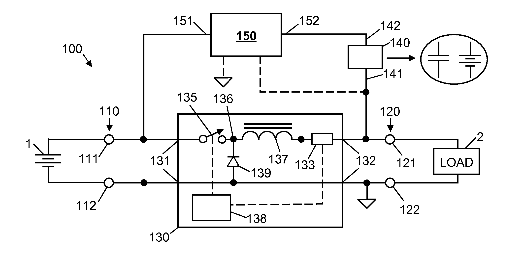
[0017]FIG. 1 shows an exemplary power supply 100 according to the present invention. Supply 100 comprises an input port 110 to receive a source of input power, an output port 120 to provide a source of output power to a load 2, a switching power supply 130, an energy storage device 140, and a coupling circuit 150. Coupling circuit 150 is coupled to energy storage device 140, switching power supply 130, and input port 110. Input port 110 has a first terminal 111 and a second terminal 112, and output port 120 has a first terminal 121 and a second terminal 122. Switching power supply 130 has an input 131 coupled to input port 110 to receive input power, an output 132 coupled to the output port 120 to provide output power, at least one switch 135, and at least one energy storage element 137. Normally, input and output capacitors would be placed at 131 and 132 respectively to improve the operation of the switching power supply 130. But because they are not germane to the description of t...


PUM


Abstract

Disclosed are novel interconnections of a coupling circuit and an energy storage device which enables the storage device to provide back-up power for a switching power supply without requiring the device to store or output high voltage, and which enables full utilization of the energy stored in the device. In exemplary embodiments, the combination of the coupling circuit and the energy storage device may be coupled between the input and output of the switching power supply (e.g., between the non-ground terminals of the input and output ports of the switching power supply). The coupling circuit is configured to couple power from the energy storage device to the input of the switching power supply when the input power source is not provided to the switching power supply, and optionally to couple power from the input power source to the energy storage device when the input power source is provided.

Description

CROSS-REFERENCES TO RELATED APPLICATIONS[0001]NOT APPLICABLEBACKGROUND OF THE INVENTION[0002]The present invention relates to power supplies, and more particularly to power supplies that can operate continuously despite interruptions of the input power source.[0003]Conventional switching power supplies convert input power having a first voltage level and a first format (e.g., AC, DC) to output power having a second voltage level and a second format, where the voltage levels and / or the formats are different. The major components employed in these circuits include input and output capacitors, switches, a temporary energy storage element, and a control circuit that senses attributes of the output (such as voltage and / or current) and regulates the operation of the switches based on that feedback. The switch is not a mechanical switch that commonly comes to mind, but electronic devices (such as a bipolar transistor, MOSFET, and diode), that operate at a high frequency upward in the kiloh...

Claims


Application Information

Patent Timeline
Patent Type & Authority Patents(United States)
IPC IPC(8): H02J1/00
CPCH02J7/345H02J7/34H02J9/061H02M2001/0096Y10T307/625H02M1/0096
Inventor WAI, PETERPUCKETTE, ROBERT
Owner TRIMBLE NAVIGATION LTD
Why Eureka
Try Eureka