Method of operating an energy system

a technology of energy system and energy system, applied in the field of energy system operation, can solve the problem of limited number of sensors and measurements required

Active Publication Date: 2021-06-17
CSEM CENT SUISSE DELECTRONIQUE & DE MICROTECHNIQUE SA RECH & DEV
View PDF0 Cites 3 Cited by
  • Summary
  • Abstract
  • Description
  • Claims
  • Application Information

AI Technical Summary

Benefits of technology

[0027]Advantageously, in said second mode a limitation is imposed on the rate of energy transfer to and/or from said external distribution network. This limitation is typically removed in said third mode, in order to stop peak shaving and prevent the state of charge moving deeper below the first state of charge or above the fourth state of charge, which could result in damage to t

Problems solved by technology

Furthermore, since the control can be carried out solely on the basis of a single factor (namely the state of charge), t

Method used


Image

  • Method of operating an energy system
  • Method of operating an energy system
  • Method of operating an energy system

Examples


Embodiment Construction

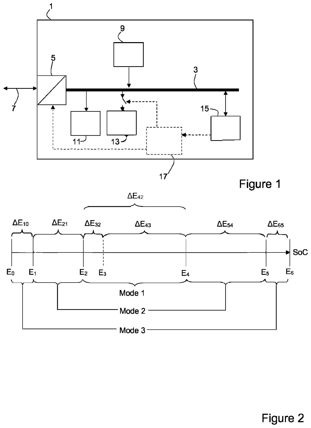
[0046]FIG. 1 illustrates generically an energy system 1 upon which the method of the invention is carried out. The system 1 may comprise a microgrid, building-scale, district scale or similarly-sized grid, as distinct from a wide network grid.

[0047]This energy system 1 may be electrical, pneumatic, thermal, hydraulic or similar, the energy in question being electrical, gas pressure, heat, or hydraulic head (i.e. pressure) respectively. In the following description, reference will be more frequently made to an electrical system, since it is the most common.

[0048]The system 1 comprises a single local common transmission bus 3 which is connected to an interface 5, which is adapted to exchange energy with an external grid 7. This external grid can for instance be an electricity grid, a compressed air network in a factory complex, a district heating network, a hydraulic system or similar, as appropriate depending on the type of energy system. The bus 3 is an energy conduit (cable, pipeli...


PUM


Abstract

Method of operating an energy system, said energy system comprising:
    • a local common transmission bus;
    • at least one local energy connected to said bus;
    • at least one local load connected to said bus;
    • an energy store connected to said bus;
    • a controllable interface arranged to exchange energy between said bus and an external distribution network external to said energy system;
    • a controller adapted to control said interface so as to carry out said exchange of energy.
According to the invention, the controller defines three modes based on the state of charge of the energy store which determine if, and how, energy is exchanged with the external network so as to optimize self-consumption and to perform ramp-rate reduction and peak shaving as appropriate.

Description

TECHNICAL FIELD[0001]The present invention relates to the technical field of energy systems. More particularly, it relates to a method of operating an energy system, in which the energy can be electrical, thermal, pneumatic, hydraulic or similar.STATE OF THE ART[0002]Currently there is a lot of interest in local microgrid energy systems integrating a local energy source such as a photovoltaic (PV) system, combined heat and power generator, wind turbines or similar, in order to produce power in a delocalized fashion and to reduce energy demand on large-scale grids. In some jurisdictions, electrical power can also be fed into the grid from such small-scale production, and sold to local energy supplier at a feed-in tariff. However, such local production rarely matches the entire profile of the local energy consumption, and is often highly variable. As a result, such systems often incorporate local energy storage such as a supercapacitor bank, battery system or similar to act as a buffe...

Claims


Application Information

Patent Timeline
IPC IPC(8): H02J3/32H02J3/38H02J3/00
CPCH02J3/32H02J3/381H02J2310/10H02J3/004H02J2300/20H02J3/003H02J3/28Y04S20/222Y02B70/3225
Inventor ROD, CHRISTIANALET, PIERRE-JEANMUSOLINO, VINCENZOKOCH, NELSON
Owner CSEM CENT SUISSE DELECTRONIQUE & DE MICROTECHNIQUE SA RECH & DEV
Why Eureka
Try Eureka