
Safety electrical outlet

a safety electrical outlet and outlet technology, applied in the direction of electrical apparatus casing/cabinet/drawer details, coupling device connections, casings/cabinets/drawers, etc., can solve the problems of difficult economic production, the possibility of accidental electrocution still exists, and the electrically conductive obj

Inactive Publication Date: 2003-11-18
LOPEZ SR RUDY A +1
View PDF27 Cites 32 Cited by
  • Summary
  • Abstract
  • Description
  • Claims
  • Application Information

AI Technical Summary

Benefits of technology

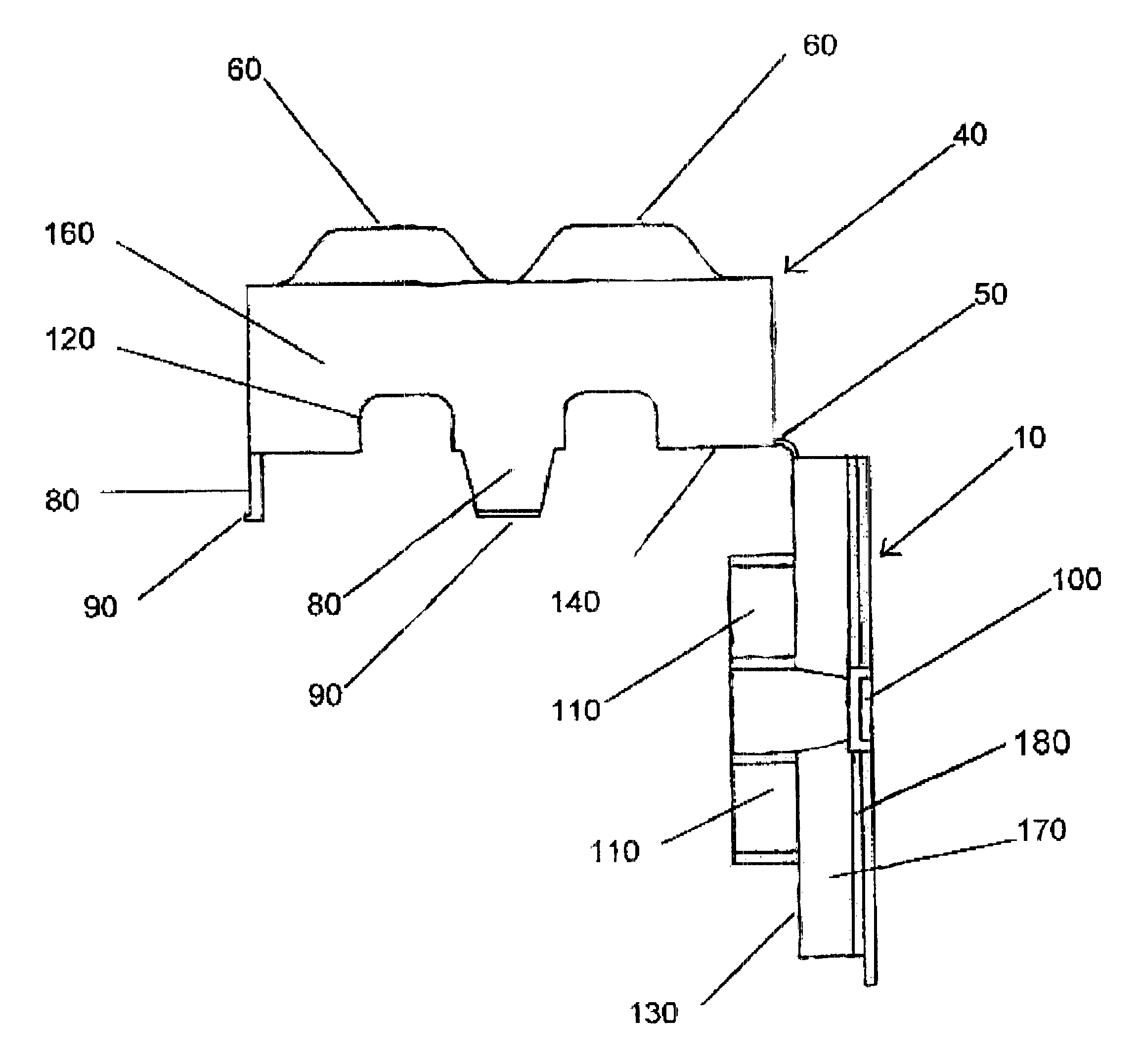
Said cover includes truncated trapezoidal protrusions aligned with the outlets of the electrical receptacle to provide clearance for the plugs and electrical cords. In this way the depth of the side walls of the cover is reduced for a better visual appearance and a reduction in the volume of material required to form the invention. For industrial and commercial applications, the protrusions and the depth of side walls can be increased to accommodate the larger plugs and electrical cords utilized in these applications.

Problems solved by technology

The patents listed above allow for passage of an electrical cord or cords through the cover but do not prevent an electrically conductive object inserted through the passage for the electrical cord from making contact with the electrical supply voltage.
Therefore the possibility of accidental electrocution still exists even with the cover in a closed position.
The device consists of multiple pieces and is of a complexity which would make it difficult to produce economically.
The arrangement of the large slot in the device provides an even greater opportunity for a young person to insert an electrically conductive object through the cover and into contact with the electrical supply voltage and therefore creates an even greater possibility of accidental electrocution.
However, none of the above-described references disclose a simple one-piece safety enclosure for installation on an electrical receptacle which completely protects a young person from accidental electrocution.
Further, even if one or more of said tabs are not positioned properly for said ridges at the tips of said tabs to lock the cover in a closed position, the cover can only be opened by the proper application of force to the appropriate tabs to release the cover.

Method used


Image

  • Safety electrical outlet
  • Safety electrical outlet
  • Safety electrical outlet

Examples


Embodiment Construction

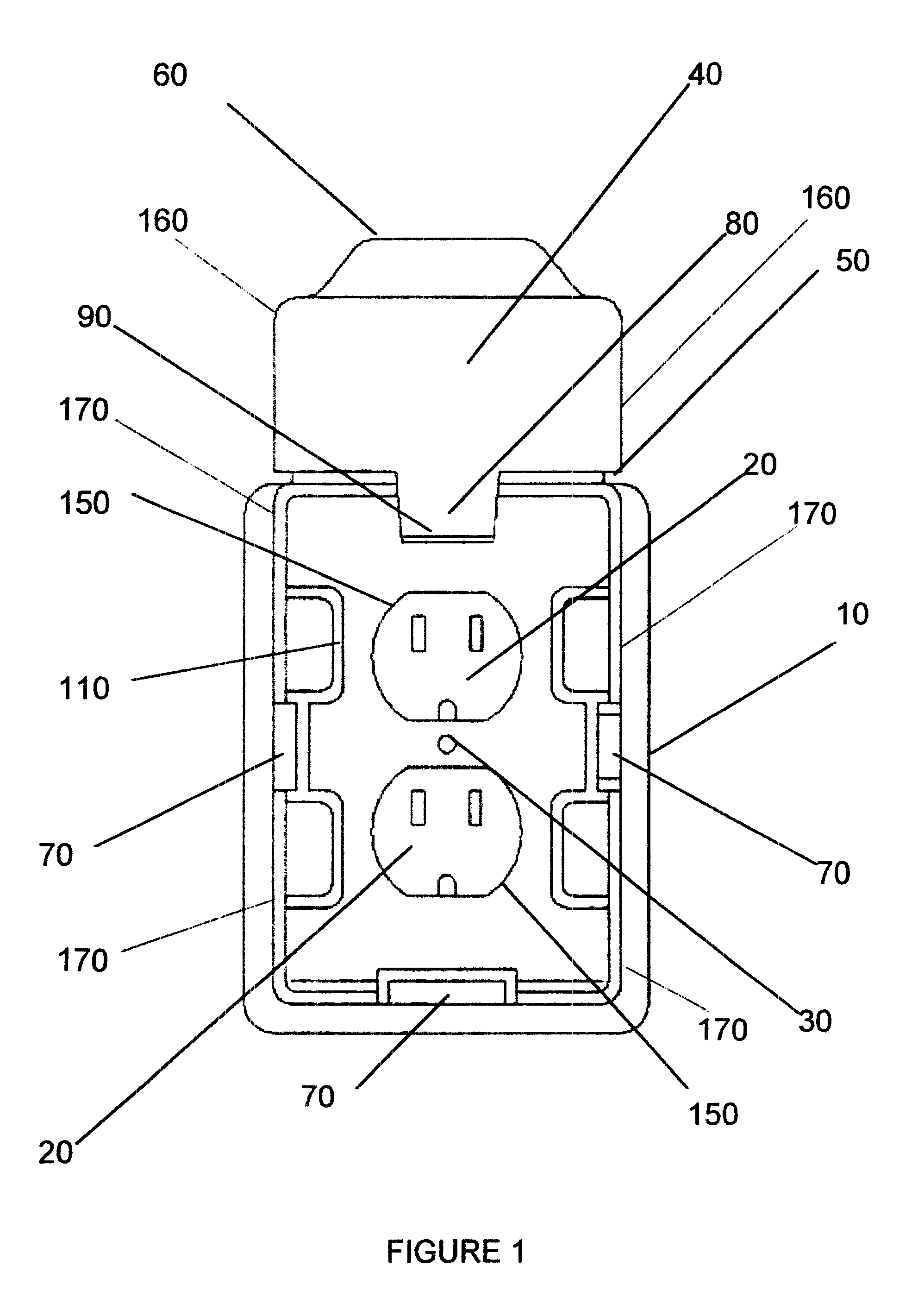
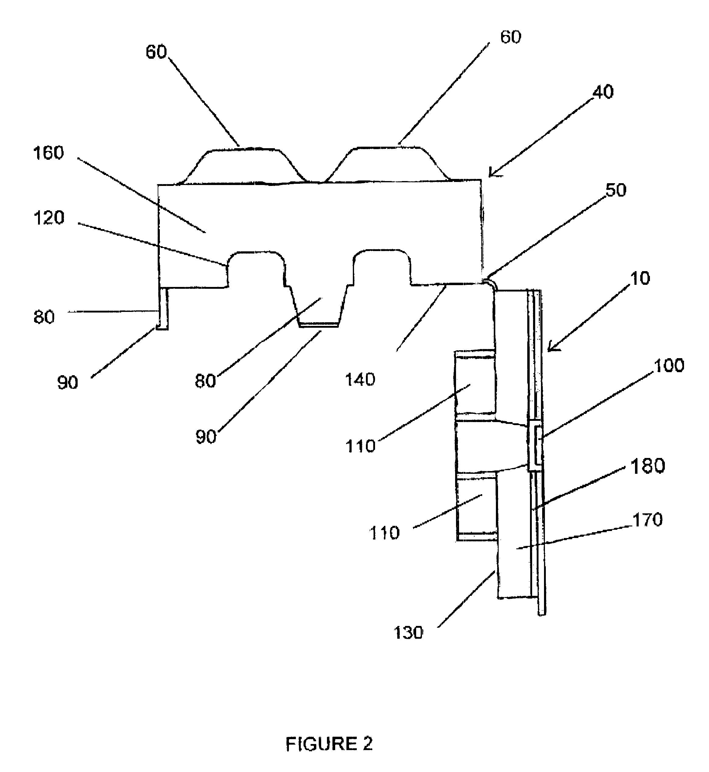
The preferred embodiment of the present invention can be best understood by reference to the drawings. FIG. 1 is a front view of the invention showing the cover in an open position. FIG. 2 is a side view of the invention showing the cover in an open position. Referring to FIG. 1, the preferred embodiment of the present invention is a one-piece structure molded or formed of a rigid fire-retardant and electrically insulating material. The invention consists of two major regions, a cover region 40 and a rigid base region 10 joined by a hinge region 50. The cover region 40 includes an open back wall 42, opposed side walls 160, and top and bottom walls 162 and 164, respectively. The hinge region 50 is created by reducing the cross-section of the material to create a flexible region in the material. The rigid base 10 is installed in place of a standard receptacle cover using a standard installation screw inserted in hole 30. The rigid base 10 provides for three notches 70 to receive the c...


PUM


Abstract

A new and improved safety outlet includes of a one-piece structure which is installed on a standard electrical receptacle in place of a standard receptacle cover. The electrical plugs installed in the outlets of the electrical receptacle are completely enclosed within the fire resistant and electrically insulating structure; baffles are incorporated into the rigid base to prevent an infant or young person from inserting a rigid object through the passages in the structure for electrical cords and thereby preventing contact with the electrical supply voltages; and three tabs spaced on three sides of the cover portion must be simultaneously pressed to allow the structure to be opened for access to the electrical plugs, thereby preventing access to the enclosed region and preventing contact with the electrical supply voltages.

Description

1. Field of the InventionThe present invention relates generally to the field of electrical outlets and more particularly to devices which cover an outlet to prevent unintentional contact with the electrical supply voltage provided by the outlet and therefore prevent accidental electrocution.2. Description of the Prior ArtThe field of devices which cover an electrical receptacle to prevent accidental contact with the electrical supply voltage has been studied extensively and a variety of approaches have been developed. This field is important due to the fact that in most installations an electrical receptacle is located such that the young, infants and toddlers, can easily access the electrical voltage provided by the outlets of the receptacle. Even though the need to protect these persons from the threat of accidental electrocution is clearly defined, the approaches to the solution of the problem vary greatly.One example is disclosed in U.S. Pat. No. 4,915,638 issued to Domian. Thi...

Claims


Application Information

Patent Timeline
Patent Type & Authority Patents(United States)
IPC IPC(8): H02G3/14
CPCH02G3/14
Inventor LOPEZ, SR., RUDY A.LOPEZ, III, EZEQUIEL R.
Owner LOPEZ SR RUDY A
Learn More