Spring scale

a technology of spring scale and spring plate, which is applied in the field of spring plate scale, can solve the problems of affecting the function, affecting the quality of the final product, and affecting the measurement accuracy, and achieves the effect of convenient assembly, easy and safe operation

Inactive Publication Date: 2003-11-18
PESOLA PRAZISIONSWAAGEN
View PDF11 Cites 13 Cited by
  • Summary
  • Abstract
  • Description
  • Claims
  • Application Information

AI Technical Summary

Benefits of technology

It is a further object of the present invention to provide a spring scale in which a spring holder and all elements connected to it in a non swivelling manner, with or without weighing goods attached, whereby the spring holder itself shall be freely swivellable, without hindering the zero point adjustment and the tare function.
This spring scale shall have a closed outer tube which protects the inner technology from contamination.
It is a further object of the present invention to provide a spring scale with individual parts which are to be produced in an economic way and are easy to assemble.
It is a further object of the present invention to provide a spring scale which shall be precisely adjustable and shall be of easy and safe operation.
The outer tube shall especially be made of a material of low density and shall in its entirety be preparable in an easy, quick and low cost way.

Problems solved by technology

This protruding cam may have frictions on the slit rims and thus may adulterate the measurement results.
Through this slit impurities may get into the interior of the spring scale and can affect proper function.
The manufacturing, the cutting of one or two threads, the printing and the colouring as well as the cutting of the slit on the outer tube are factors, which increase the price of the final product substantially.
Such a mounting increases the price of the spring scale.
The regulating range of the spring bearing on the set screw can not be limited to one side, whereby it is possible that the set screw can be completely unscrewed from the spring bearing and thus the spring scale may completely lose its operability.

Method used


Image

  • Spring scale
  • Spring scale
  • Spring scale

Examples


example

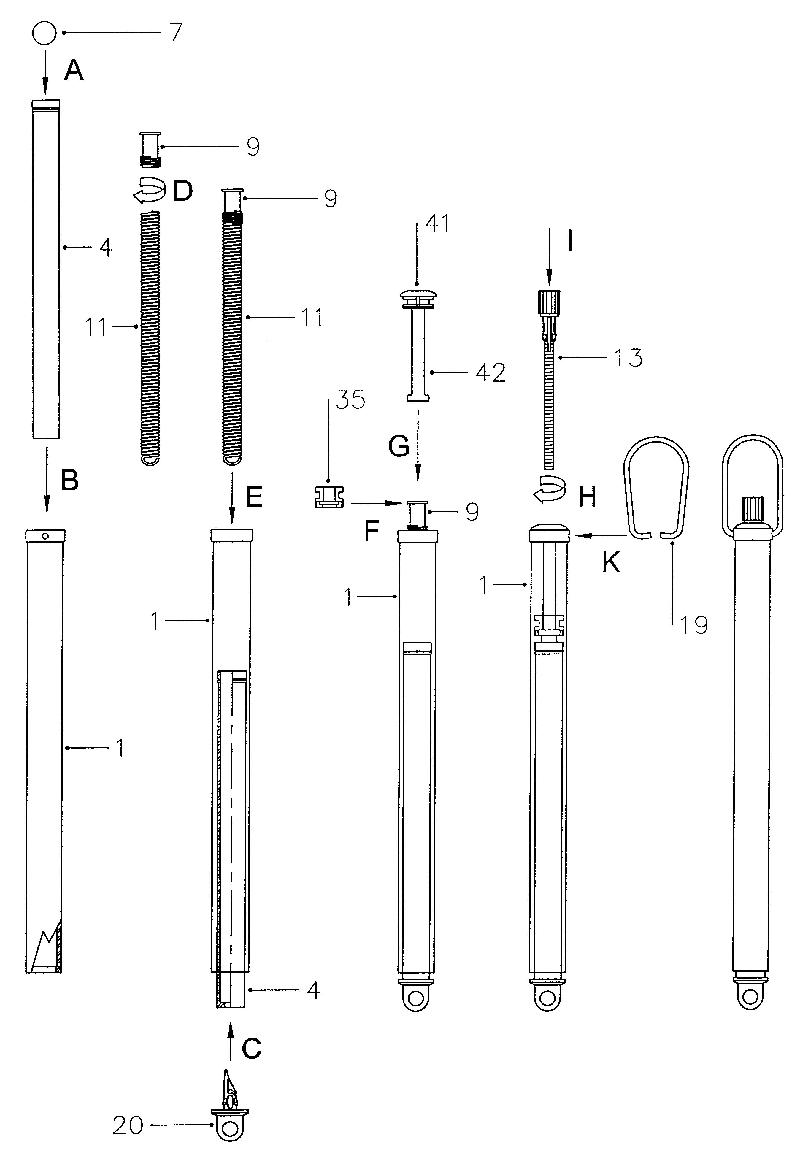
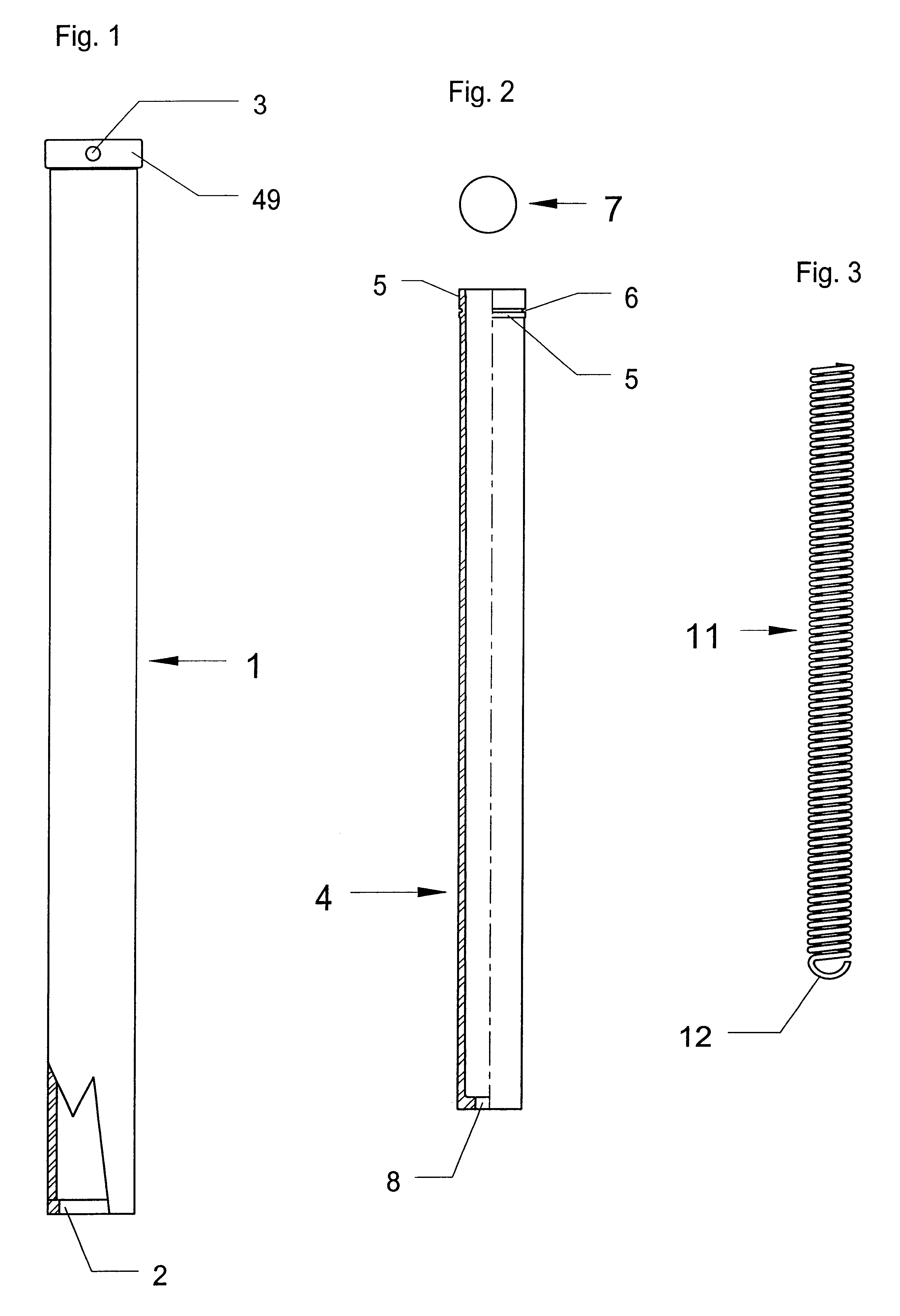
The inner tube 4 made of polyoxymethylene (POM) in an injection moulding process has a total length of 116.5 mm and an outside diameter of 9.1 mm. At the circulating cylindrical, concentric, 4 mm long thickening 5 the outside diameter is 9.5 mm. Into this thickening 5 is cut a 0.5 mm deep, circulating groove 6, in which is inserted an adapted, red O-ring 7, in accordance with FIG. 11, step A. The end of the inner tube 4, which is opposite to the thickening 5, has a bottom with a centric whole 8 having a diameter of 4.1 mm.

The transparent cylindrical outer tube 1 made of polyoxycarbonate (PC) in an injection moulding process has a total length of 152.8 mm and an outside diameter of 12.2 mm. The outer tube 1 has on one end a protruding, circulating 4 mm long collar 49 with an outside diameter of 13.5 mm. The collar 49 has two opposite holes 3 with a diameter of 1.8 mm and at its inner wall a recess. The end of the outer tube 1, opposite to the collar 49, has on its inside a circulatin...


PUM


Abstract

The spring scale according to present invention comprises an outer tube (1), an inner tube (4) with an O-ring (7), an end eye (20), a spring holder (9), a spiral spring (11), a set screw (13), a hanger (19), a holder bearing (35) as well as a cover (41) with spur (42).

Description

This application claims priority under 35 U.S.C. .sctn..sctn.119 and / or 365 to Swiss Patent Application No. 2000 1912 / 00 filed in Switzerland on Sep. 29, 2000; the entire content of which is hereby incorporated by reference.DESCRIPTION OF THE PRIOR ARTConventional spring scales with double tube technology have a non transparent outer tube with a slit with graduations along its sides. An inner tube with a protruding cam is inserted into an outer tube. The cam has marking functions while moving up and down in the graduation slit. This protruding cam may have frictions on the slit rims and thus may adulterate the measurement results. This protruding cam hinders the free rotation of the inner tube.Through this slit impurities may get into the interior of the spring scale and can affect proper function.The measurement graduation may only be read in the range of the slit.Due to reasons of the measuring accuracy and stability such spring scales must almost conclusively have an outer tube m...

Claims


Application Information

Patent Timeline
Patent Type & Authority Patents(United States)
IPC IPC(8): G01G3/00G01G3/02
CPCG01G3/02
Inventor STROHMEIER, ROLF MARTIN
Owner PESOLA PRAZISIONSWAAGEN
Why Eureka
Try Eureka