
System and method for actively changing an effective flow-through area of an inlet region of an aircraft engine

Inactive Publication Date: 2003-12-02
GENERAL ELECTRIC CO
View PDF19 Cites 102 Cited by
  • Summary
  • Abstract
  • Description
  • Claims
  • Application Information

AI Technical Summary

Benefits of technology

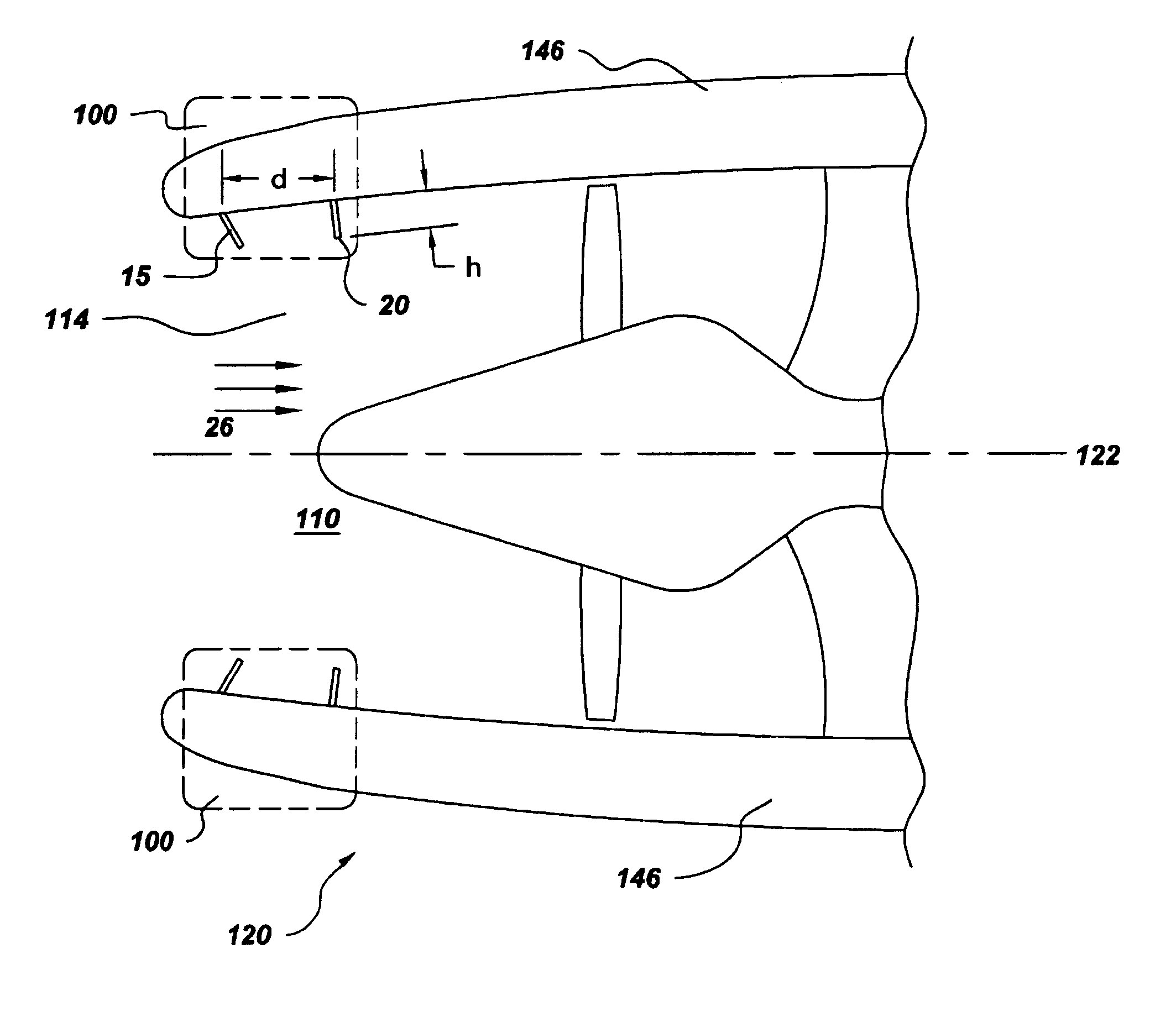
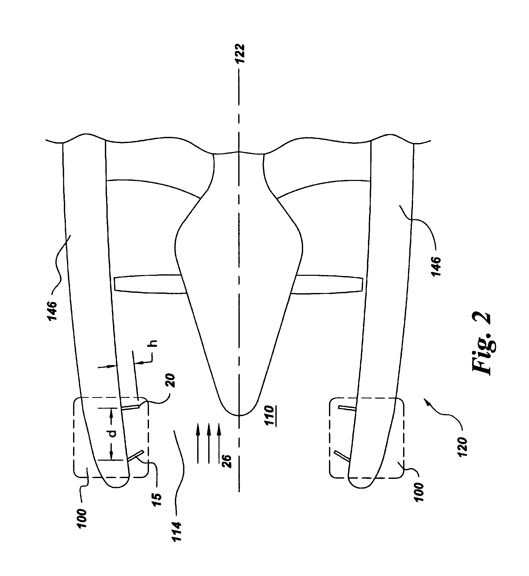
Briefly, in accordance with one embodiment of the present invention, an active effective flow-though area control system includes an upstream wall-flow perturber and a downstream wall-flow perturber situated in an inlet region of an aircraft engine. The downstream wall-flow peturber is positioned downstream from the upstream wal-flow perturber. The upstream and downstream wall-flow peturbers are configured to generate and trap at lease one region of separated, vortical flow in the airflow through the inlet region.
For another embodiment of the invention, a variable effective flow-through area inlet of an aircraft engine is disclosed. The variable effective flow-through area inlet includes an inner wall defining

Problems solved by technology

The amount of noise that is generated by an aircraft engine during the takeoff and landing of an aircraft continues to be a concern and is often limited by government regulation.
Sources of noise for aircraft engines include fan and inlet noise.

Method used


Image

  • System and method for actively changing an effective flow-through area of an inlet region of an aircraft engine
  • System and method for actively changing an effective flow-through area of an inlet region of an aircraft engine
  • System and method for actively changing an effective flow-through area of an inlet region of an aircraft engine

Examples


Embodiment Construction

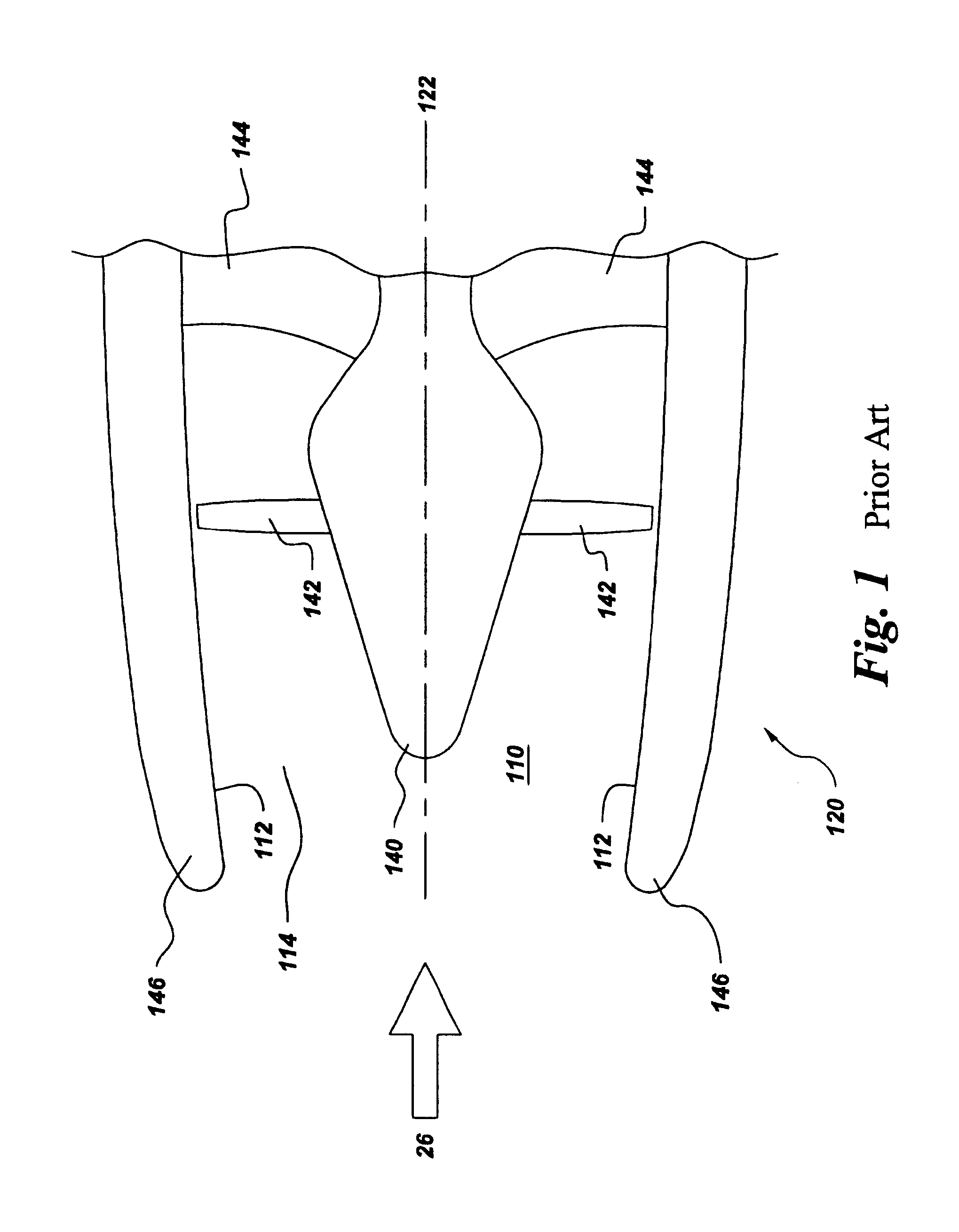
By way of background, a forward portion of an exemplary aircraft turbofan engine 120 is described with reference to FIG. 1. Aircraft engine 120 includes a spinner 140, which is configured to rotate fan, or rotor, blades 142 about longitudinal centerline axis 122. Surrounding fan blades 142 is a nacelle 146, which includes an inner wall 112 defining an inlet region 110. Ambient air 26 flows into inlet region 110 during operation of aircraft engine 120. A number of circumferentially spaced apart outlet guide vanes (OGVs), or stator vanes, 144 extend radially about longitudinal centerline axis 122 and are spaced axially downstream from rotor blades 142.

During operation of aircraft engine 120, rotor blades 142 are caused to rotate about centerline axis 122 by a core engine (not shown). It is known that rotation of rotor blades 142 generates loud noise, which may be objectionable during takeoff and landing operations of aircraft engine 120. It is an object of the present invention to red...


PUM


Abstract

An active effective flow-through area control system includes an upstream wall-flow perturber and a downstream wall-flow perturber situated in an inlet region of an aircraft engine. The downstream wall-flow perturber is positioned downstream from the upstream wall-flow perturber. The upstream and downstream wall-flow perturbers are configured to generate and trap at least one region of separated, vortical flow in the airflow through the inlet region. A method, for actively changing an effective flow-through area of an inlet region of an aircraft engine, includes creating at least one region of separated, vortical flow in an airflow passage defined by the inlet region. The method further includes trapping the region of separated, vortical flow in the airflow passage. The region of separated, vortical flow partially obstructs a main inlet airflow.

Description

BACKGROUND OF INVENTIONThe invention relates generally to an inlet of an aircraft engine and, more particularly, to a system and method for actively changing an effective flow-though area of the inlet, to vary the Mach number of airflow through the inlet.The amount of noise that is generated by an aircraft engine during the takeoff and landing of an aircraft continues to be a concern and is often limited by government regulation. Sources of noise for aircraft engines include fan and inlet noise. Accordingly, it would be desirable to develop a system and a method for reducing fan and inlet noise during takeoff and landing operations. It would further be desirable for the system and method to avoid reducing performance characteristics of the aircraft engine during the remainder of the flight.SUMMARY OF INVENTIONBriefly, in accordance with one embodiment of the present invention, an active effective flow-though area control system includes an upstream wall-flow perturber and a downstre...

Claims


Application Information

Patent Timeline
IPC IPC(8): B64C23/00B64C23/06B64D33/02B64D33/00B64D29/06F01D17/00F02C7/042F02C7/045F02C7/057F02K3/06F04D27/00F04D29/54
CPCB64C23/06B64D33/02F02C7/042F02C7/045B64D2033/0286F05D2240/14Y02T50/162Y02T50/672F05D2220/323F05D2240/126Y02T50/10Y02T50/60
Inventor GUPTA, ANURAGGRAZIOSI, PAOLOMANI, RAMANI
Owner GENERAL ELECTRIC CO
Learn More