
Fuel supply amount control apparatus for internal combustion engine

a technology of internal combustion engine and amount control, which is applied in the direction of electrical control, process and machine control, instruments, etc., can solve the problem of no technique for estimating air-fuel ratio

Inactive Publication Date: 2004-01-06
DENSO CORP
View PDF11 Cites 13 Cited by
  • Summary
  • Abstract
  • Description
  • Claims
  • Application Information

AI Technical Summary

Problems solved by technology

However, there is no technique to estimate an air-fuel ratio (hereinafter referred to "A / F") from the variation amount of the rotation speed Ne instead of the determination of fuel properties.

Method used


Image

  • Fuel supply amount control apparatus for internal combustion engine
  • Fuel supply amount control apparatus for internal combustion engine
  • Fuel supply amount control apparatus for internal combustion engine

Examples


Embodiment Construction

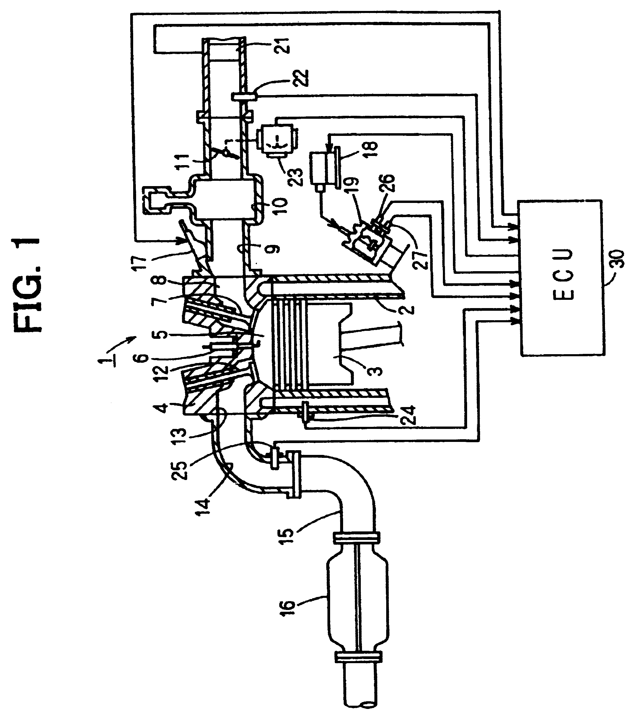
FIG. 1 shows the system configuration of an engine including a fuel supply amount control apparatus according to the embodiment.

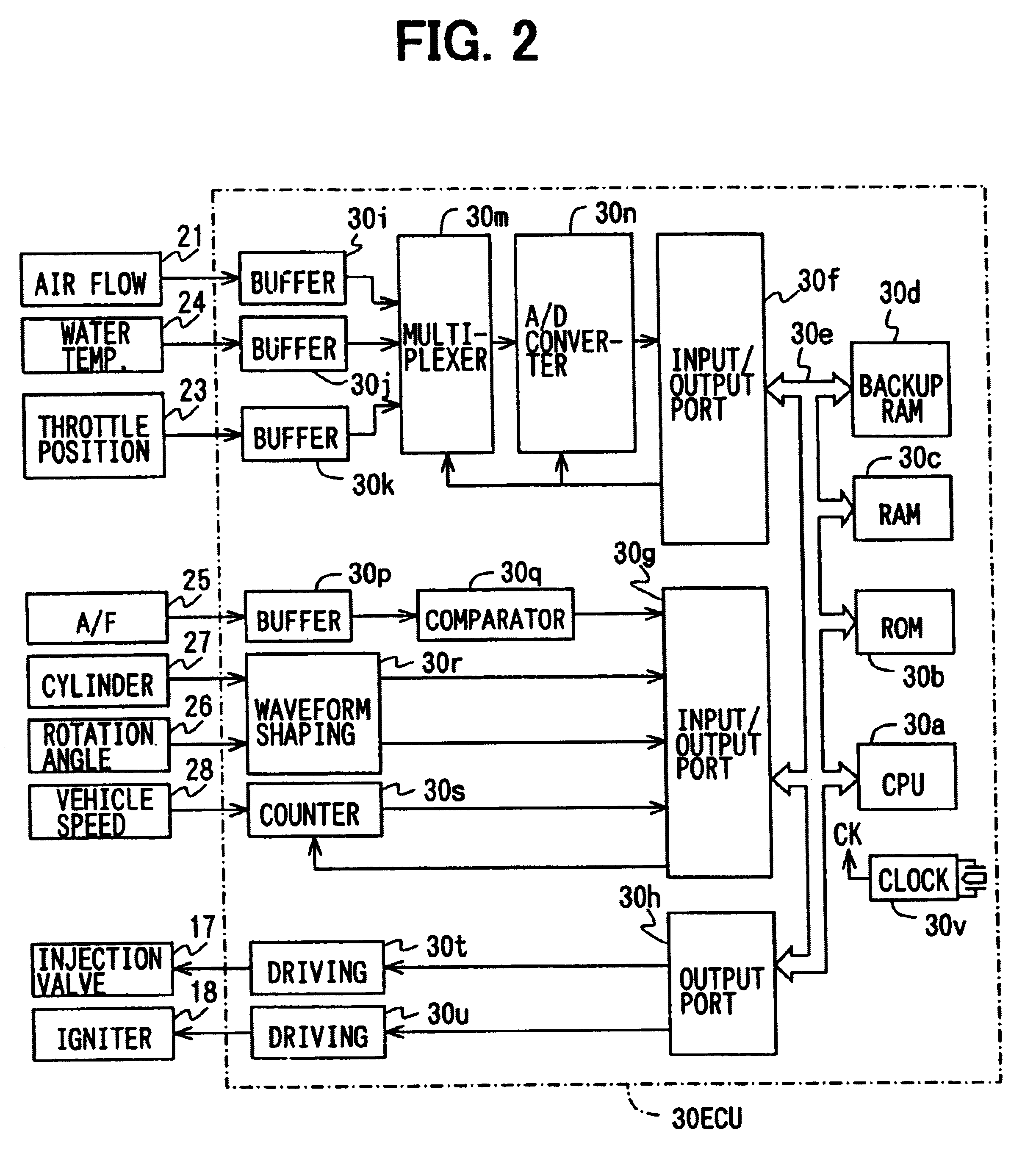
As shown in FIG. 1, an engine 1 has a combustion chamber 5 formed with a cylinder 2, a piston 3 and a cylinder head 4. The combustion chamber 5 is provided with an ignition plug 6. An intake system of the engine 1 is provided with an intake port 8 communicated with the combustion chamber 5 via an intake valve 7, an intake manifold 9 connected to the intake port 8, a surge tank 10 which absorbs the pulse of intake air, and a throttle valve 11 which controls the amount of intake air. The throttle valve 11 is driven by a DC motor (not illustrated), and controlled to a throttle opening appropriate to a driving state. On the other hand, an exhaust system of the engine 1 is provided with an exhaust port 13 communicating with the combustion chamber 5 through an exhaust valve 12, an exhaust manifold 14 communicated with the exhaust port 13, an exhaust pipe 15 which...


PUM


Abstract

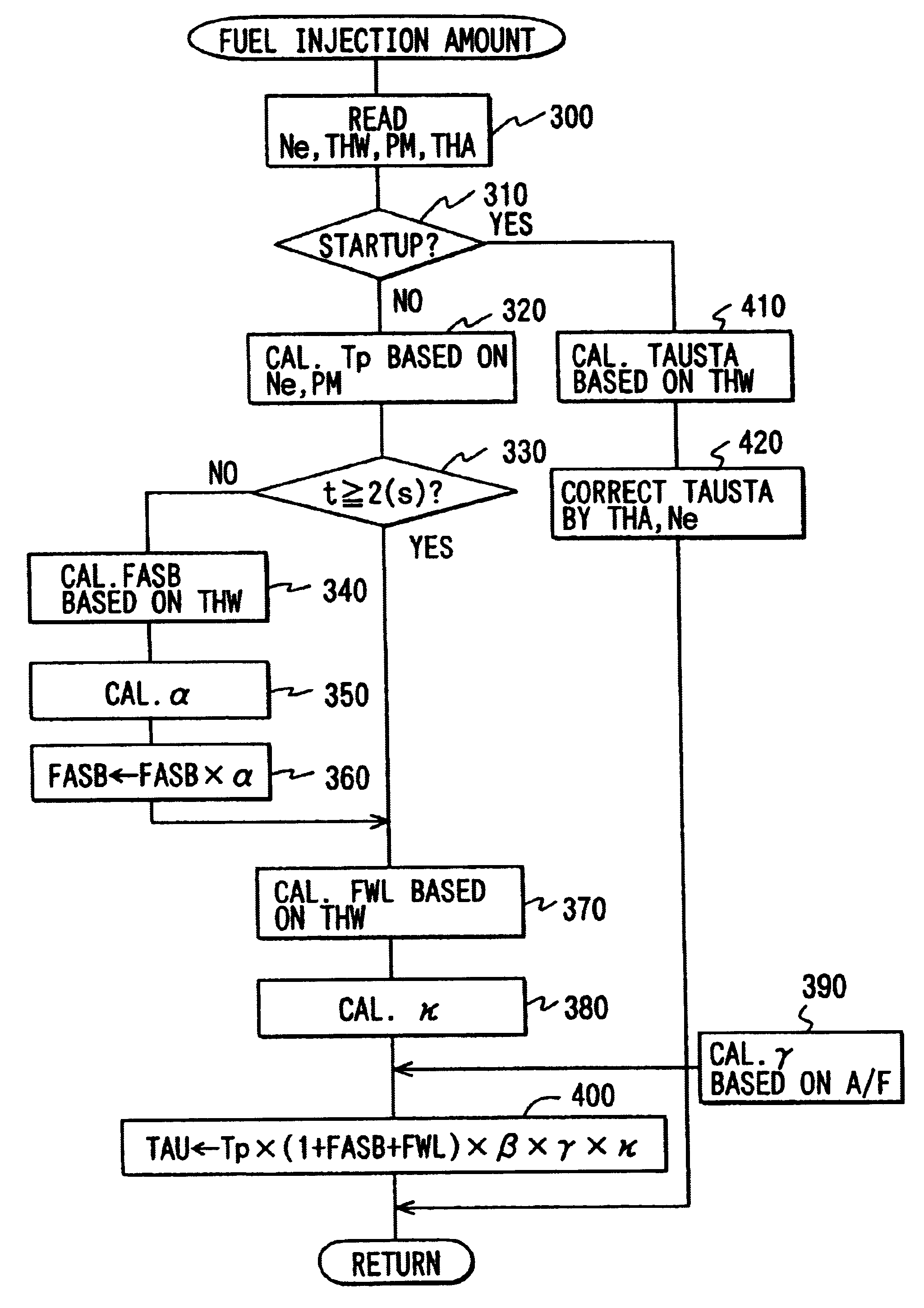
When control conditions are satisfied, an A / F value is estimated from an average value of rotation speed Ne and an increasing rotation speed DeltaNe calculated. The estimated A / F value as a base is obtained from the average value of the rotation speed Ne, and a correction value for the estimated A / F value is obtained from the increasing rotation speed DeltaNe. Then, a fuel increment / decrement correction coefficient gamma and an air increment / decrement correction coefficient beta are calculated, and used in the control of A / F ratio toward a target A / F value based on a final estimated A / F value.

Description

This application is based on and incorporates herein by reference Japanese Patent Application No. 2000-317812 filed on Oct. 18, 2000.1. Field of the InventionThe present invention relates to an apparatus to control an amount of fuel supply to an internal combustion engine.2. Description of Related ArtConventionally, a technique to determine the properties of fuel based on variations in rotation speed Ne upon or immediately after startup of internal combustion engine is known.However, there is no technique to estimate an air-fuel ratio (hereinafter referred to "A / F") from the variation amount of the rotation speed Ne instead of the determination of fuel properties.An object of the present invention is to provide an internal combustion engine fuel supply amount control apparatus to estimate an A / F based on the rotation speed Ne of the engine and accurately control the air-fuel ratio immediately after startup of the engine based on the estimated A / F.According to the present invention i...

Claims


Application Information

Patent Timeline
Patent Type & Authority Patents(United States)
IPC IPC(8): F02D41/06F02D41/14F02D45/00F02D13/02F02D41/04
CPCF02D41/062F02D41/1458F02D41/1498F02D41/187F02D2200/0414F02D2200/0614F02D2200/1012F02D2200/1015
Inventor MAJIMA, YOSHIHIRO
Owner DENSO CORP
Learn More