Pressure plate assembly

a technology of pressure plate and assembly, which is applied in the direction of friction clutches, interengaging clutches, and clutches, etc., can solve the problems of unplanned wear-compensating adjustment, blockage elements that can interact with the gripping elements, and complicated process

Inactive Publication Date: 2004-01-06
ZF FRIEDRICHSHAFEN AG
View PDF7 Cites 0 Cited by
  • Summary
  • Abstract
  • Description
  • Claims
  • Application Information

AI Technical Summary

Benefits of technology

As a result of the design of a pressure plate assembly according to the invention, in which, in the state before the assembly is connected to a centrifugal mass arrangement, the blocking element is ultimately unable to interact with the gripping element, there is basically no danger that unwanted movement of the pressure plate during transport will cause an undesirable wear-compensating adjustment of the wear-compensating device. Because it is impossible for the blocking element to interact with the gripping element, there is basically no need to provide additional transport-securing measures to make sure that the pressure plate is held in a pulled-back position relative to the housing arrangement. The pressure plate could ultimately be held in the desired position relative to the housing arrangement simply by the elements which connect the pressure plate to the housing arrangement such as tangential leaf springs, provided that they are strong enough. But if additional transport-securing devices are to be provided anyway to reduce the load on the tangential leaf springs, for example, these springs would then not have to be strong enough to pull the pressure plate all the way back and hold it there. Instead, a small movement toward the housing arrangement is enough to provide the tangential leaf springs with the load relief mentioned above; and, because of the small extent of this movement or stroke, the force exerted by the stored-energy element in the area of the transport-securing devices is also much smaller.
In the pressure plate assembly according to the invention, it is also preferable for the blocking element to pass through an opening provided in the housing arrangement, which opening allows relative motion between the housing arrangement and the blocking element; for the area of the blocking element situated inside the housing arrangement to enter into a blocking interaction with the associated gripping element; and for the area of the blocking element outside the housing arrangement to be fixed in place relative to the housing arrangement. Because the blocking element projects outward beyond the housing arrangement, it becomes easier to exert an effect on the blocking element, i.e., either to produce the blocking interaction or to bring the blocking element into a position which allows the blocking interaction to take place.

Problems solved by technology

This results in the problem that, after the assembly comprising the housing arrangement and the blocking element has been put together with the assembly comprising the pressure plate, the wear-compensating device, and the clearance-producing device, there is the potential danger that the blocking element can interact with the gripping element of the clearance-giving arrangement, this danger being caused by the pretensioning force existing between the housing arrangement and the pressure plate and by the absence of any support for the pressure plate at this stage of assembly, i.e., before the pressure plate assembly has been connected to the centrifugal mass arrangement.
The result of such interaction would be the unwanted completion of a wear-compensating adjustment, even though no wear had yet occurred.
The provision of such transport-securing devices, however, which must hold the stored-energy element in a highly pretensioned position, is a complicated process, especially because of the fact that the transport-securing devices must be massive enough and attached with sufficient permanence that the stored-energy element, which usually generates a comparatively large amount of force, is held securely in the tensioned state indicated above.
But if additional transport-securing devices are to be provided anyway to reduce the load on the tangential leaf springs, for example, these springs would then not have to be strong enough to pull the pressure plate all the way back and hold it there.

Method used


Image

  • Pressure plate assembly
  • Pressure plate assembly
  • Pressure plate assembly

Examples


Embodiment Construction

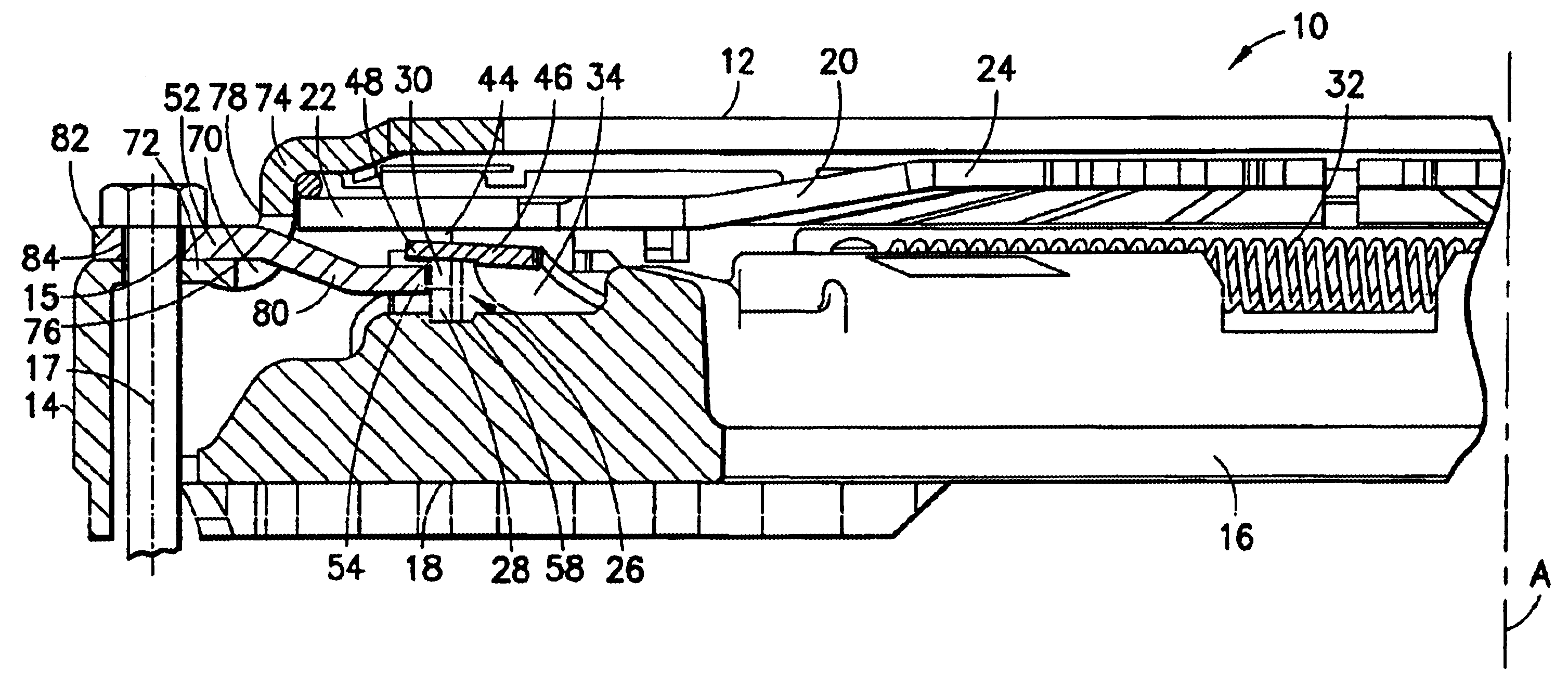
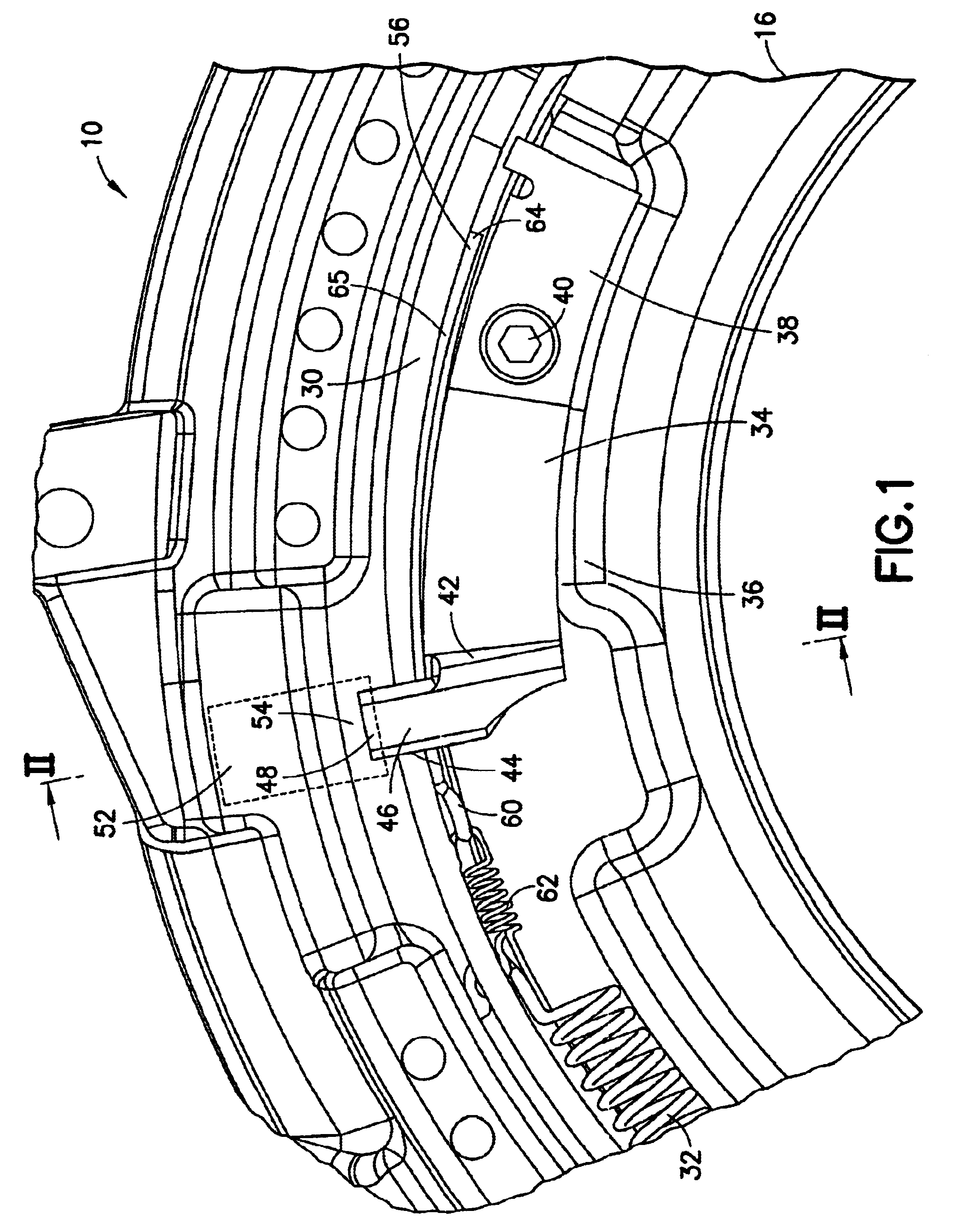
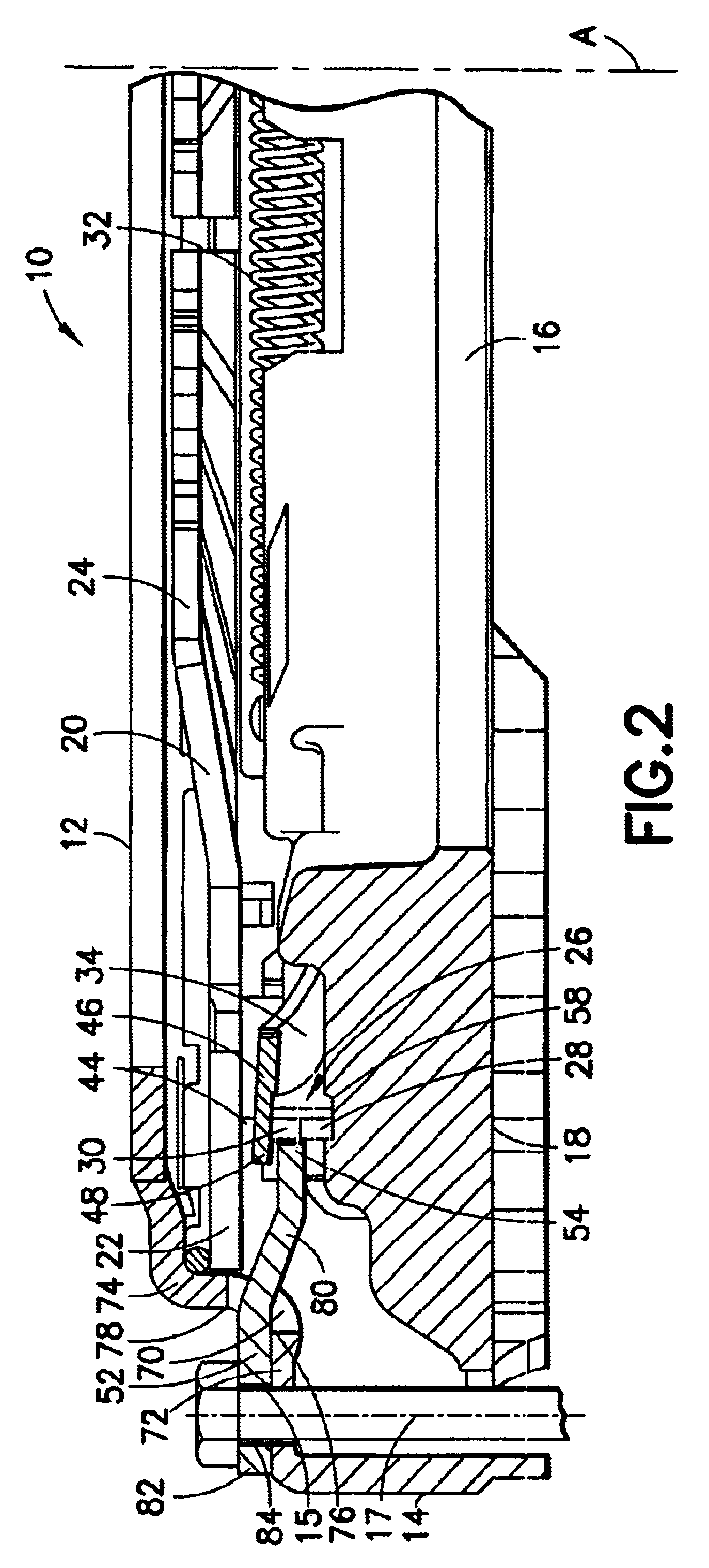
The pressure plate assembly 10 shown in FIGS. 1 and 2 comprises a housing 12, which is designed to be connected to a centrifugal mass arrangement (not shown in the figures) such as a single-mass flywheel or possibly a multiple-mass flywheel. The radially outer edge area 14 of the housing arrangement 12 points toward the centrifugal mass arrangement, and the free axial end of this area can have end stops, for example, which determine the relative axial positioning between the housing arrangement 12 and the centrifugal mass arrangement. The housing arrangement 12 and thus the entire pressure plate assembly 10 is fixed in position relative to the centrifugal mass arrangement by a plurality of threaded bolts 17, which pass through openings 15, which are distributed around the housing arrangement 12 in the circumferential direction, which bolts can be screwed into assigned openings in the centrifugal mass arrangement. To arrive at the required relative axial positioning here between the ...


PUM


Abstract

A pressure plate assembly for a friction clutch includes a housing for mounting to a centrifugal mass; a pressure plate, which is mounted in the housing with freedom to move in the same direction as that in which a rotational axis (A) extends; a stored-energy element; and a wear-compensating device, acting in the path of force transmission between the stored-energy element and the pressure plate, where the wear-compensating device has at least one adjusting element able to move in an adjusting direction to compensate for wear. A clearance-producing arrangement includes a gripping element provided on the pressure plate, which, when wear occurs, comes to rest or can be brought to rest against a blocking element, which is fixed or can be fixed in place relative to the housing arrangement. During or after the connection of the housing arrangement to the centrifugal mass arrangement, the blocking element arrives in or can be brought into a state in which it can enter into a blocking interaction with the associated gripping element.

Description

1. Field of the InventionThe present invention pertains to a pressure plate assembly for a friction clutch, comprising a housing arrangement designed to be connected to a centrifugal mass arrangement; a pressure plate held in the housing arrangement with freedom to move axially; a stored-energy element; a wear-compensating device acting in the path of force transmission between the stored-energy element and the pressure plate, where the wear-compensating device has at least one adjusting element able to move in an adjusting direction to compensate for the wear; and at least one clearance-producing arrangement, comprising a gripping element on the pressure plate, which element, when wear occurs, comes to rest or can be brought to rest against a blocking element, which is fixed or can be fixed in place relative to the housing arrangement.2. Description of the Related ArtA pressure plate assembly of this type is known from, for example, U.S. Pat. No. 6,123,180. In this known pressure p...

Claims


Application Information

Patent Timeline
Patent Type & Authority Patents(United States)
IPC IPC(8): F16D13/58F16D13/75
CPCF16D13/757F16D2013/581F16D2300/12
Inventor WEIDINGER, REINHOLDZIEGLER, ERWINHIRSCHMANN, FRANK
Owner ZF FRIEDRICHSHAFEN AG
Why Eureka
Try Eureka