
Method and apparatus for performing a minimally invasive total hip arthroplasty

a hip arthroplasty and minimally invasive technology, applied in the field of total hip arthroplasty, can solve the problems of long rehabilitation time of patients, weeks or perhaps months before the soft tissue violated during surgery can be fully healed,

Inactive Publication Date: 2004-01-13
ZIMMER INC
View PDF48 Cites 175 Cited by
  • Summary
  • Abstract
  • Description
  • Claims
  • Application Information

AI Technical Summary

Benefits of technology

The present invention provides an improved method and apparatus for performing a minimally invasive total hip arthroplasty. The method involves making two incisions, one on the front and one on the back, through which the surgeon can perform the procedure. The first incision is made in line with the femoral neck and the central axis of the acetabulum, while the second incision is made in the femoral shaft. The method allows for a more efficient and minimally invasive procedure, reducing the time required for recovery and rehabilitation. The invention is suitable for cemented or cementless anchorage of the components and can be performed using a total hip replacement or a bipolar or monopolar endo prosthesis. The apparatus includes a femoral stem and an acetabular cup that can be inserted through the incisions. The invention provides a more efficient and minimally invasive method for performing a total hip replacement.

Problems solved by technology

While this approach provides surgeons with an excellent view of the bone surface, the underlying damage to the soft tissue, including the muscles, can lengthen a patient's rehabilitation time after surgery.
While the implants may be well fixed at the time of surgery, it may be several weeks or perhaps months before the soft tissues violated during surgery can be fully healed.

Method used


Image

  • Method and apparatus for performing a minimally invasive total hip arthroplasty
  • Method and apparatus for performing a minimally invasive total hip arthroplasty
  • Method and apparatus for performing a minimally invasive total hip arthroplasty

Examples


Embodiment Construction

makes reference to a nested posterior retractor configuration. It will be understood by those skilled in the art that if the nested configuration is not utilized, each individual component of posterior retractor 122 will be inserted and removed through posterior incision 46 as necessary.

FIG. 16 illustrates preparation of femoral canal 148 to receive rasp 204 (FIG. 19). Guide tube 124 is removed from posterior retractor 122 and end cutter 150 (FIG. 17A) is inserted through reamer tunnel 126. FIG. 18 illustrates end cutter 150 positioned within reamer tunnel 126. End cutter 150 includes elongate aperture 160 through which guide wire 146 passes and guides end cutter 150. End cutter 150 is actuated by any of the many actuating devices known in the art. After end cutting is complete, end cutter 150 is removed through reamer tunnel 126 and reamer 151 (FIG. 17B) is inserted therethrough. Reamer 151 includes reamer guide aperture 161 through which guide wire 146 passes an guides reamer 151 ...


PUM


Abstract

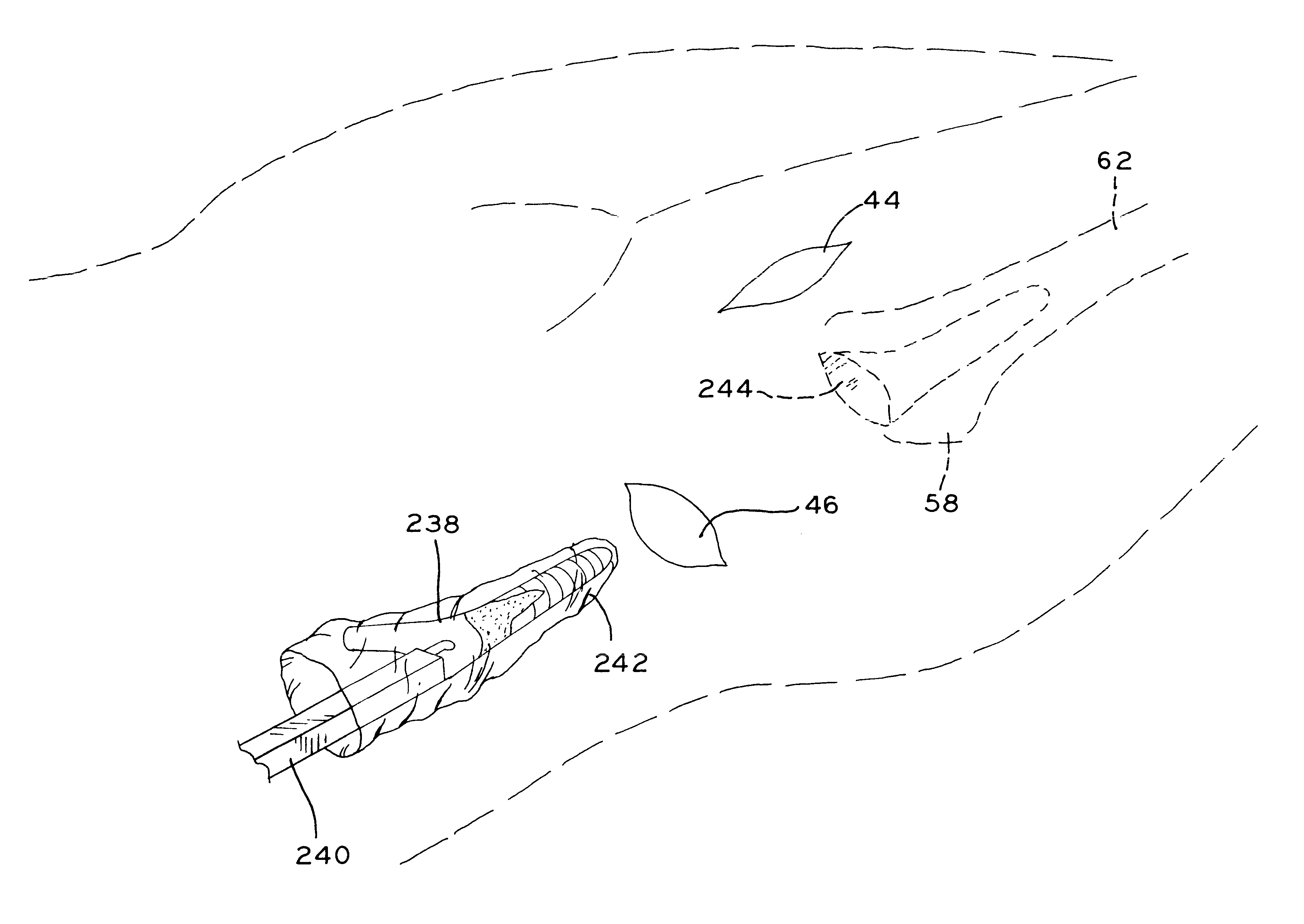
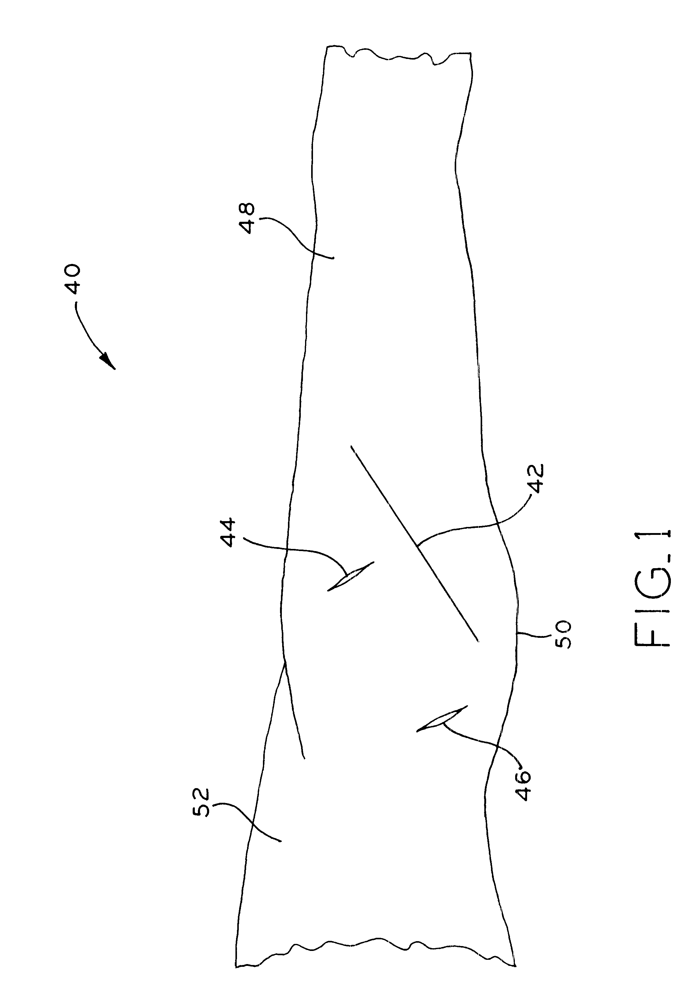
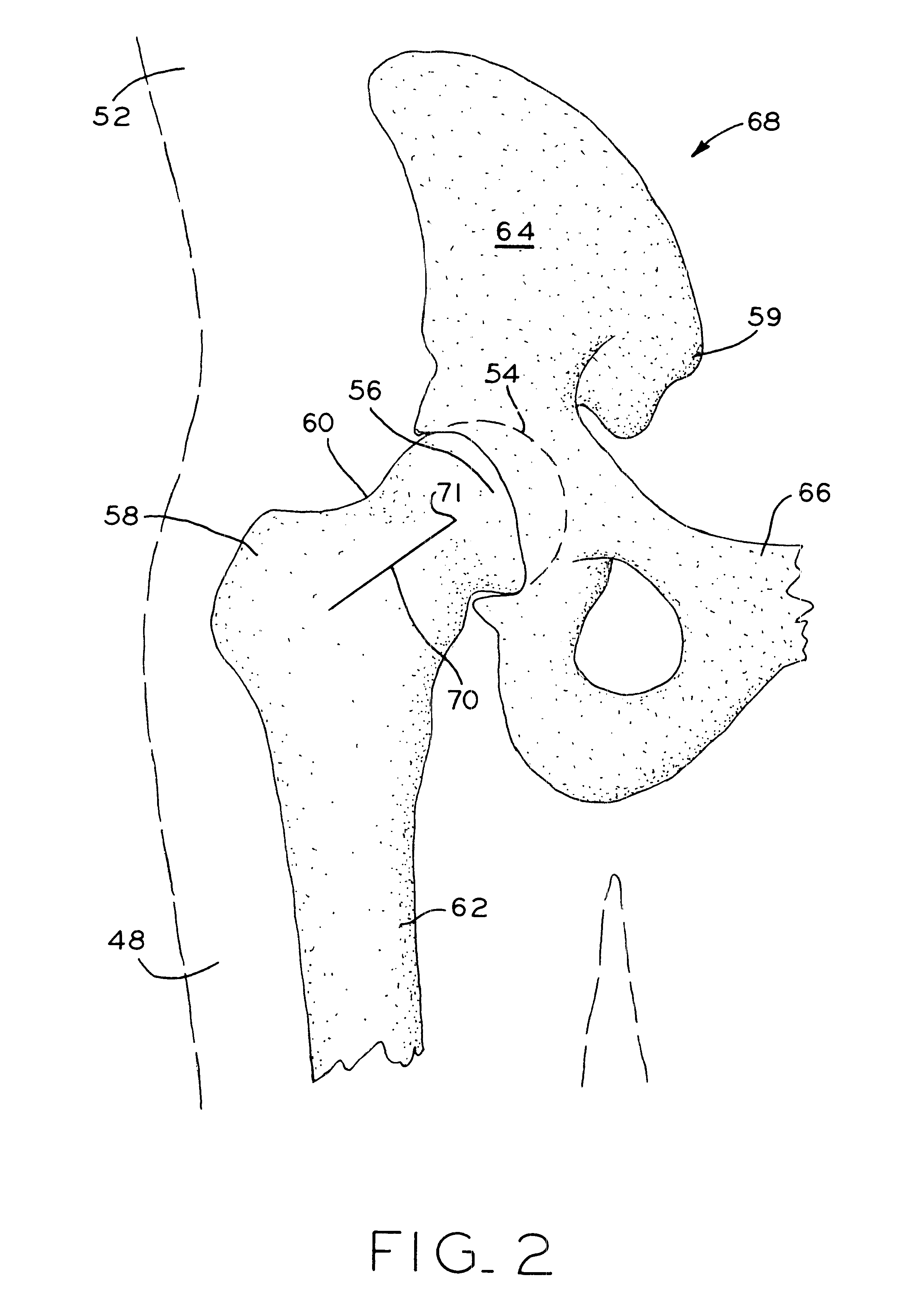
A method and apparatus for performing a minimally invasive total hip arthroplasty. An approximately 3.75-5 centimeter (1.5-2 inch) anterior incision is made in line with the femoral neck. The femoral neck is severed from the femoral shaft and removed through the anterior incision. The acetabulum is prepared for receiving an acetabular cup through the anterior incision, and the acetabular cup is placed into the acetabulum through the anterior incision. A posterior incision of approximately 2.5-3.75 centimeters (1-1.5 inches) is generally aligned with the axis of the femoral shaft and provides access to the femoral shaft. Preparation of the femoral shaft including the reaming and rasping thereof is performed through the posterior incision, and the femoral stem is inserted through the posterior incision for implantation in the femur. A variety of novel instruments including an osteotomy guide; an awl for locating a posterior incision aligned with the axis of the femoral shaft; a tubular posterior retractor; a selectively lockable rasp handle with an engagement guide; and a selectively lockable provisional neck are utilized to perform the total hip arthroplasty of the current invention.

Description

1. Field of the InventionThe present invention relates to total hip arthroplasty, and, more particularly, to a method and apparatus for performing a minimally invasive total hip arthroplasty.2. Description of the Related ArtOrthopaedic procedures for the replacement of all, or a portion of, a patient's joint have been developed over the last 30 years. Currently, the procedures used to prepare the bone and seat the implants are-generally referred to as open procedures. For the purpose of this discussion, the term open procedure will refer to a procedure wherein an incision is made through the skin and underlying tissue to fully expose a large portion of the particular joint surface. In the case of a total hip arthroplasty, the typical incision required is approximately 25 centimeters (10 inches) long. After the initial incision in the skin, the internal wound may be enlarged in order to fully expose the areas to be prepared. While this approach provides surgeons with an excellent vie...

Claims


Application Information

Patent Timeline
Patent Type & Authority Patents(United States)
IPC IPC(8): A61B17/14A61B17/17A61B17/16A61B17/15A61B17/34A61F2/46A61G13/00A61B17/00B25B13/06B25B13/00B25B13/48B25B7/02B25B7/00B27G17/00B27G17/06F16D3/20F16D3/16A61B19/00A61F2/00A61F2/32A61F2/34A61F2/36A61B17/02A61B17/56
CPCA61B17/00234A61B17/02A61B17/14A61B17/15A61B17/151A61B17/164A61B17/1659A61B17/1668A61B17/1735A61B17/175A61B17/3421A61F2/4607A61F2/4609A61F2/4684A61G13/0036B25B7/02B25B13/06B25B13/48B25B13/481B27G17/06F16D3/20A61B17/148A61B17/0293A61B17/1796A61B17/8866A61B17/8872A61B2017/0046A61B2019/481A61F2/0095A61F2/32A61F2/34A61F2/36A61F2002/30718A61F2002/3404A61F2002/3611A61F2002/3621A61F2002/3625A61F2002/4623A61F2002/4624A61F2002/4629A61F2002/4635A61F2002/4681A61F2002/4622A61F2002/4627A61F2002/4628A61F2/4603A61F2002/3403A61B2090/08021A61B17/142A61B17/144
Inventor MEARS, DANAGREIG, KEVINZWIRKOSKI, PAUL A.
Owner ZIMMER INC
Learn More