Object detecting device with a pyroelectric sensor

a technology of infrared radiation sensor and object detecting device, which is applied in the direction of optical radiation measurement, counting objects on conveyors, instruments, etc., can solve the problems of frequent replacement of batteries, device power consumption, prior device waste of power,

Inactive Publication Date: 2004-01-13
MATSUSHITA ELECTRIC WORKS LTD
View PDF7 Cites 14 Cited by
  • Summary
  • Abstract
  • Description
  • Claims
  • Application Information

AI Technical Summary

Benefits of technology

The mode selector is designed to keep the operation mode continuously for a predetermined time frame from the first advent of the detection signal and to switch it back to the standby mode thereafter for avoiding unnecessary power consumption after the object detection. In this connection, the mode selector is preferred to reset the time frame to start each time the detection signal is followed by another detection signal within the time frame, thereby extending the operation mode for successive and reliable detection of the object.
The mode selector may be provided with a reset input for receiving a reset signal from the external device. When the reset input is enabled, the mode selector operates to switch the operation mode forcibly into a rest mode of keeping the limited source current to be supplied to the voltage amplifier and at the same time disabling the level monitor upon seeing the first advent of the detection signal, and keeps the rest mode until receiving the reset signal at the reset input. Thus, the device can be interlocked or closely associated with the external device so as to keep the power consumption at a minimum level while the external device is reacting to make a dedicated function such as turning on an illumination appliance in response to the control output, thereby reducing the power consumption.
In order to start the device rapidly for reliable detection, the mode selector is preferred to supply an initialization current greater than the rated source current to the voltage amplifier only for a predetermined initialization time period immediately upon energization of the device. Further, the mode selector is preferred to select the rest mode for a predetermined stabilization time period immediately subsequent to the initialization time period, and to switch the rest mode into the standby mode thereafter. Thus, the voltage amplifier inherently requiring much initialization current can be rapidly made ready for reliable operation. After the stabilization time period, the components of the device can be made stable to be ready for reliable detection, while eliminating a possibility of causing erroneous circuit operation leading to a false detection due to unstable outputs of the voltage amplifier during the stabilization time period.
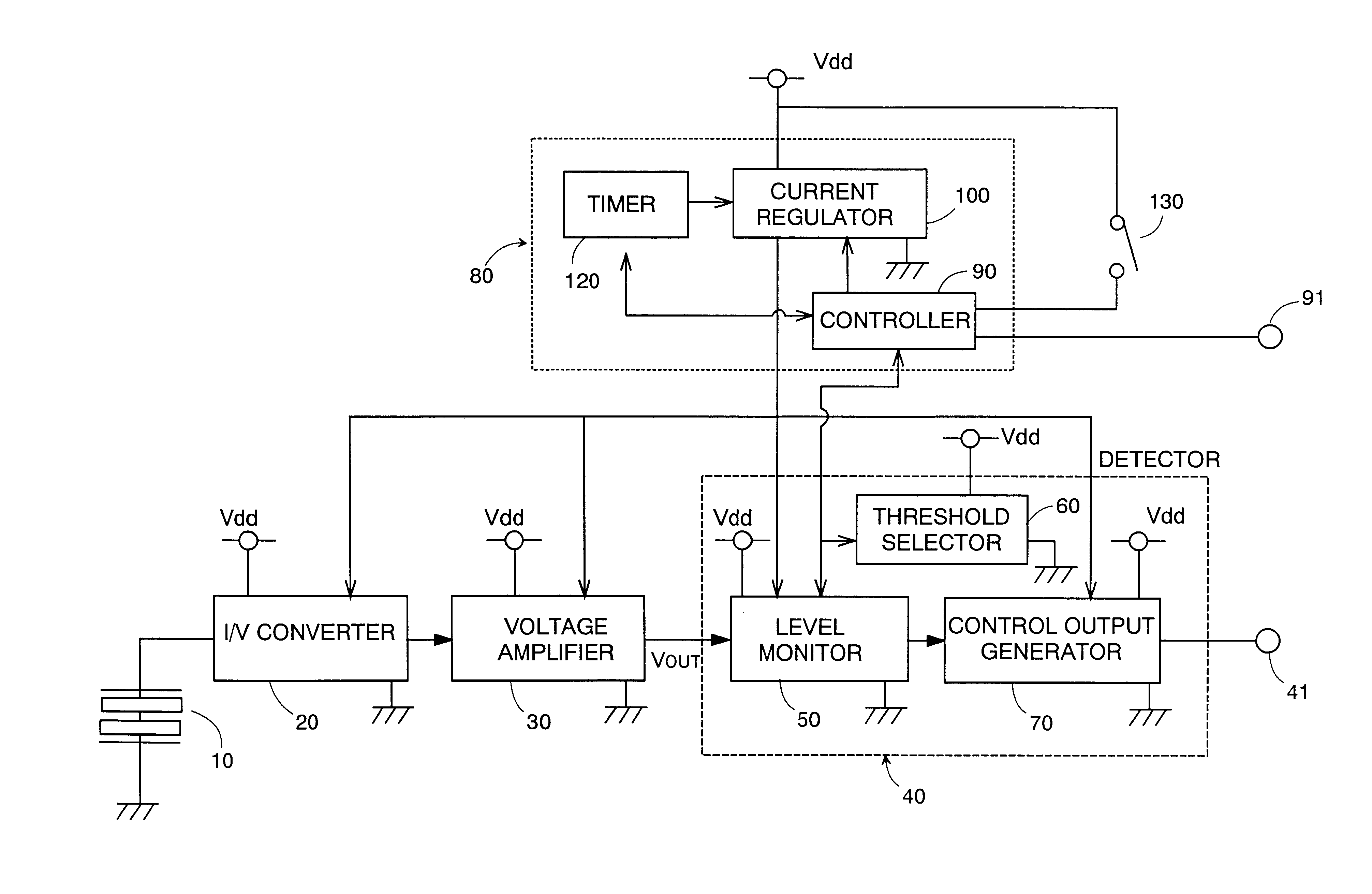
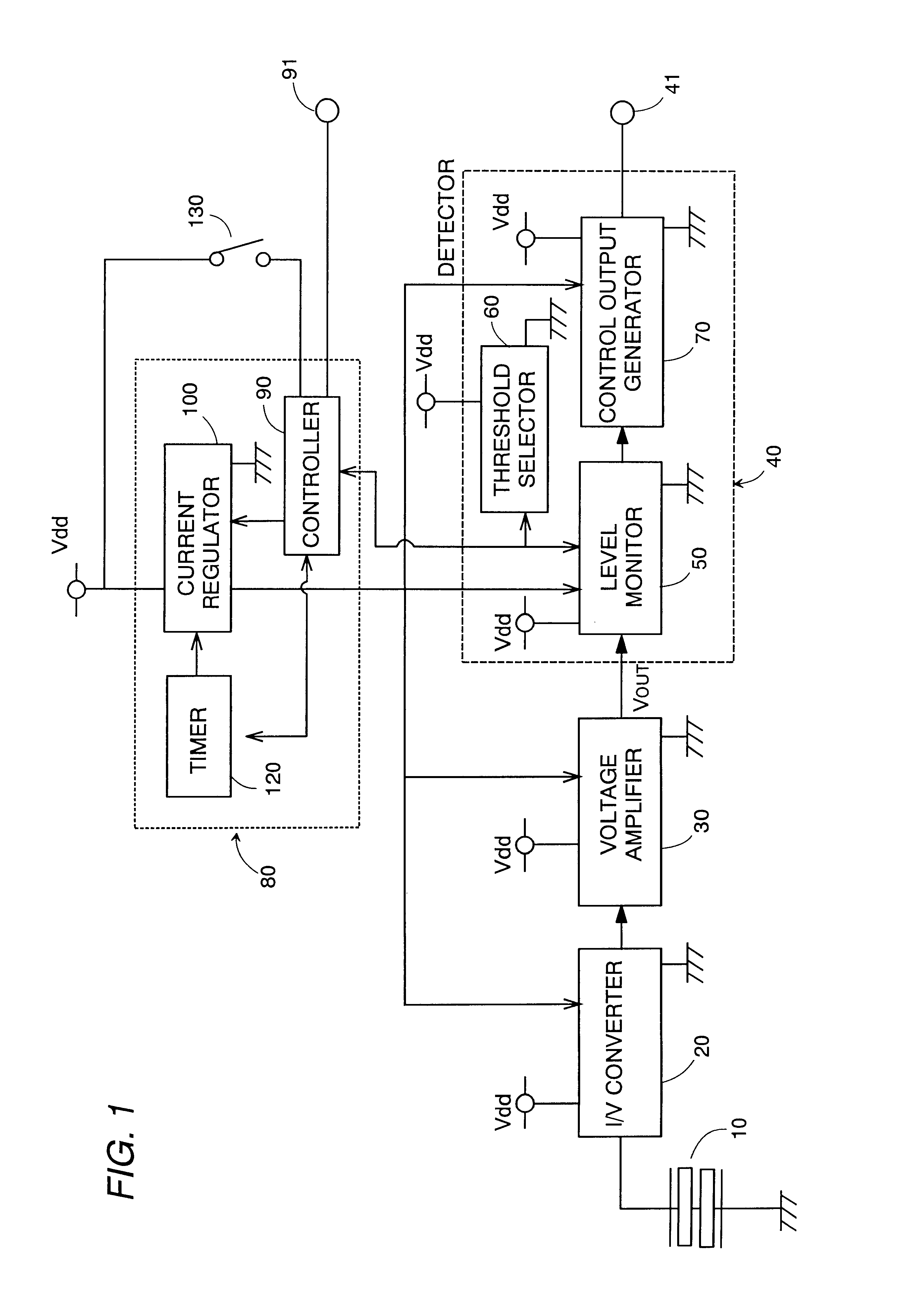
The voltage amplifier may be of two-stage amplifier having a front-stage amplifying section and a rear-stage amplifying section. In this connection, the mode selector is configured to supply the limited source current to the front-stage and rear-stage amplifying sections in the standby mode, and supply the limited source current to the front-stage amplifying section and the rated source current to the rear-stage amplifying section in the operation mode. With the use of the two-stage amplifier and the associated scheme of only changing the level of the current being fed to the rear-stage amplifying section, it is made possible to further reduce the power consumption as compared to a case where the entire current to the amplifier is changed from the limited level to the rated level.
Further, the voltage amplifier is preferred to generate the rated voltage output which saturates at a level just above the detection threshold for the purpose of minimizing the power consumption in the operation mode, yet retaining reliable detection.
Preferably, the threshold selector includes a first voltage divider providing the preliminary threshold from a reference voltage and a second voltage divider providing the detection threshold from the same reference voltage. The first voltage divider is composed of a series combination of first resistors, while the second voltage divider is composed of a series combination of second resistors. The first resistor is selected to have a higher resistance than the second resistor in order to realize an advantageous effect of reducing the power consumption made at the first voltage divider to give the preliminary threshold with the use of the first resistors of high resistance, while enabling the second voltage divider to give the detection threshold accurately with the use of the second resistors of low resistance. Because of that first and second resistors are preferably selected from those that can be integrated in a chip for circuit miniaturization of the device, and also because of that the resistors of the type available can give an accurate resistance value as the intended resistance lowers, the second voltage divider makes the use of the second resistors of low resistance to provide the accurate the detection threshold for reliable object detection therewith, while the first voltage divider can consumes less power with the use of the first resistors of high resistance in providing the preliminary threshold which is not critical for object determination and could be rough as compared to the detection threshold. For instance, the first resistor may be selected from a non impurity-doped polysilicon resistor and a MOS (metal oxide semiconductor) transistor, while the second resistor may be selected from an impurity-doped polysilicon resistor.

Problems solved by technology

Accordingly, the device will consume the power even in the absence of the infrared radiation of a level not causing the detection signal, i.e., in the absence of the human body.
Thus, the prior device wastes the power and has to require frequent replacements of a battery when it is used as the power source for the device.

Method used


Image

  • Object detecting device with a pyroelectric sensor
  • Object detecting device with a pyroelectric sensor
  • Object detecting device with a pyroelectric sensor

Examples


Embodiment Construction

Referring now to FIG. 1, there is shown an object detecting device in accordance with a preferred embodiment of the present invention. The device is utilized for surveillance of a room or the like space and is adapted to be interlocked with an external device such as an illumination appliance, an alarm and the like for activating the external device upon detection of a human body in the room. The device utilizes a pyroelectric sensor 10 which generates a sensing current in proportion to changes in the amount of incident infrared radiation from the human body. The sensing current is fed to an I / V converter 20 where it is converted into a corresponding voltage. The voltage is then amplified at a voltage amplifier 30 to provide a voltage output to a detector 40 for detection of the human body. The amplifier 30 has an offset voltage VOFT around which the voltage output VOUT varies, as shown in FIG. 4, in proportion to the amount of the sensing current from the pyroelectric sensor 10.

The...


PUM


Abstract

An object detecting device utilizes a pyroelectric sensor providing a sensing current, a voltage amplifier providing an amplified voltage proportional to the sensing current, and a level monitor providing a detection signal when the amplified voltage exceeds a detection threshold. The device has a standby mode where the voltage amplifier receives a limited source current to provide the voltage of low amplification, and the level monitor provides a wake-up signal when the low amplified voltage exceeds a preliminary threshold lower than the detection threshold. In response to the wake-up signal, the device is switched to an operation mode where the amplifier receives a rated source current to provide a voltage of high amplification for comparison with the detection threshold. Thus, the amplifier is kept to be less-power consuming in the absence of the wake-up signal, reducing a power requirement.

Description

1. Field of the InventionThe present invention is directed to an object detecting device with the use of a pyroelectric infrared radiation sensor, and more particularly a surveillance device for detecting the presence of a human in a room or space.2. Description of the Prior ArtA typical object detecting device is disclosed in Japanese Utility Model Publication No. 2-9891 and Japanese Patent Publication No. 6-3366. The device utilizes a pyroelectric sensor generating a sensing current upon receiving an infrared radiation from a human body, and an I / V converter that converts the sensing current into a voltage. The device requires a voltage amplifier which amplifies the voltage from the I / V converter to an amplified voltage of a level sufficiently enough to be compared with a threshold for discriminating the presence of the human body. When the amplified voltage exceeds the threshold, a detector provides a detection signal which is then processed to issue a control output for activati...

Claims


Application Information

Patent Timeline
Patent Type & Authority Patents(United States)
IPC IPC(8): G01J5/10G01J5/34G08B13/191G08B13/189G01V8/10
CPCG01J5/34G08B13/191G01V8/10
Inventor HIRONAKA, ATSUSHIIKARI, MOTOOTAKADA, YUJIMATSUDA, HIROSHIMURAYAMA, YORINOBU
Owner MATSUSHITA ELECTRIC WORKS LTD
Why Eureka
Try Eureka