
Process for the phase amplitude demodulation of a received radar signal and device implementing such a process

a technology of received radar and phase amplitude demodulation, which is applied in the direction of amplitude demodulation, measurement devices, instruments, etc., can solve the problems of secondary lobes at the output of doppler filters, complicated signal processing devices, and inability to implement devices that are not always simpl

Inactive Publication Date: 2004-01-13
THOMSON CSF SA
View PDF8 Cites 9 Cited by
  • Summary
  • Abstract
  • Description
  • Claims
  • Application Information

AI Technical Summary

Problems solved by technology

These faults can be compensated for by adjustment loops associated with very powerful computation algorithms but despite everything they remain an element limiting the performance of radar signal processing devices.
In particular they cause a rising of secondary lobes at the output of the Doppler filters which is undesirable.
The implemented devices are not however always simple and sometimes complicate the production of signal processing devices.

Method used


Image

  • Process for the phase amplitude demodulation of a received radar signal and device implementing such a process
  • Process for the phase amplitude demodulation of a received radar signal and device implementing such a process
  • Process for the phase amplitude demodulation of a received radar signal and device implementing such a process

Examples


first embodiment

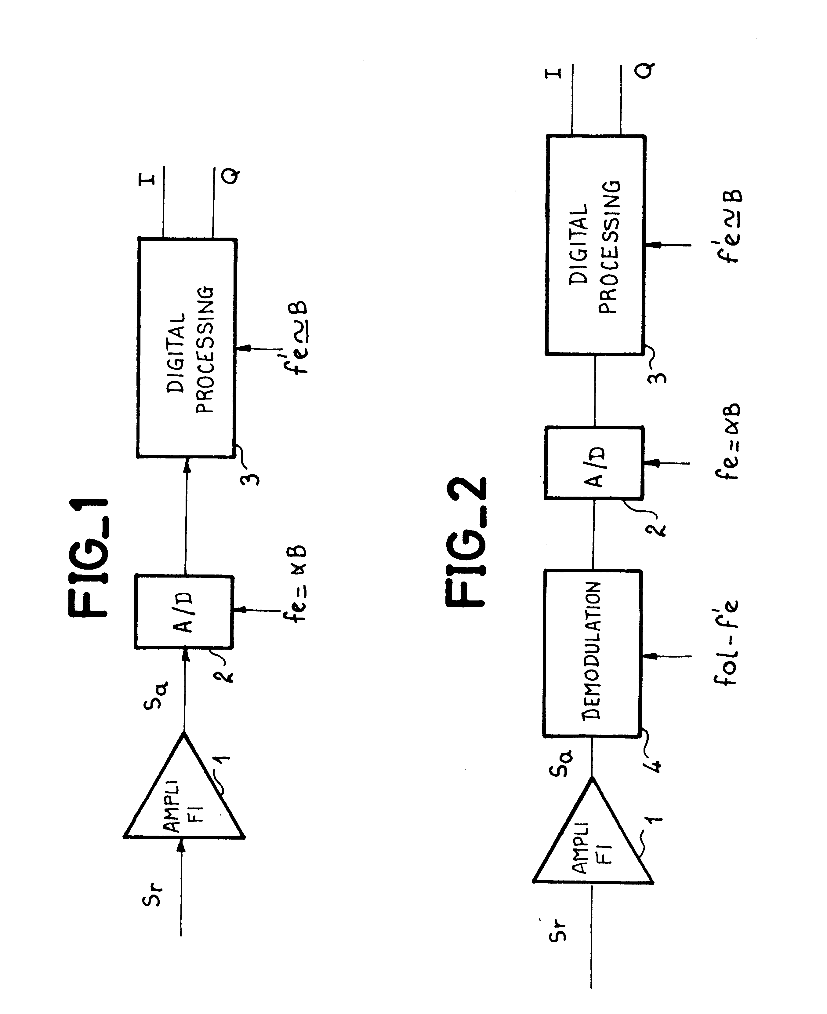
The general block diagram of the device implementing the process according to the invention is shown in FIG. 1. It is a first embodiment wherein the device includes an intermediate frequency amplifier 1, an analog-digital converter 2, and a digital processing circuit 3. The amplifier 1 receives the radar signal S.sub.r transposed into intermediate frequency and amplifies it. The amplified signal S.sub.a is sampled by the converter 2 at a frequency of f.sub.e equal to .alpha.B, the sampled signal then being processed by circuit 3. This processing consists in particular in carrying out a sub-sampling at a frequency f'.sub.e such that f'.sub.e is approximately equal to B.

second embodiment

FIG. 2 shows a second embodiment wherein the amplified intermediate frequency signal is demodulated by a demodulator 4 by a signal at intermediate frequency f'.sub.i such that f'.sub.i is equal to f.sub.0L -f.sub.e / 4, f.sub.0L being the frequency of the receiver's local oscillator. The signal coming from the demodulator 4 is sampled at frequency f.sub.e, f.sub.e =.alpha.B. The sampled signal is processed by the processing circuit 3.

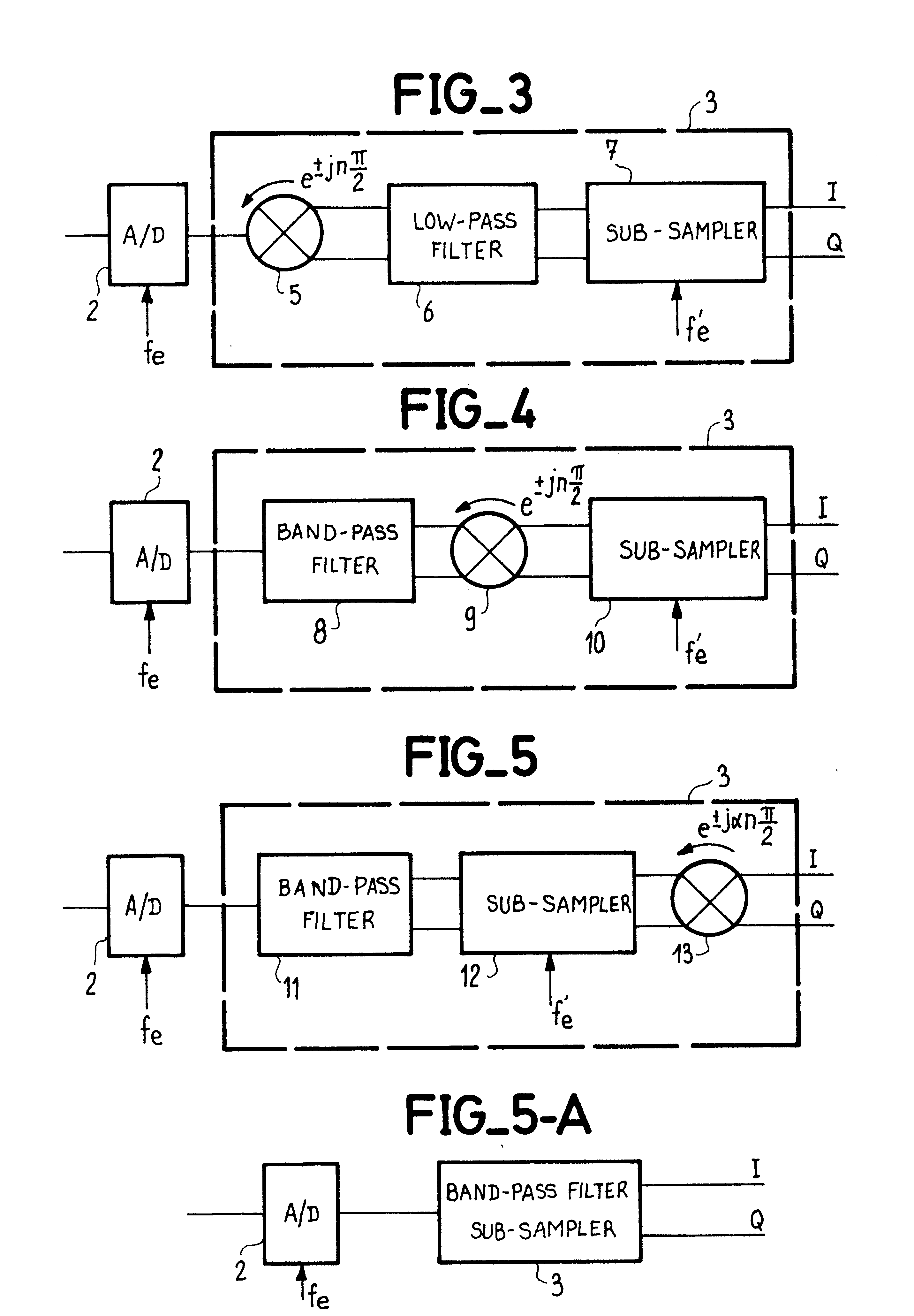
FIGS. 3, 4 and 5 show the basic block diagrams of the processing circuit according to three variant embodiments.

According to the first variant the circuit 3 includes firstly a demodulator 5 which brings the useful signal into baseband, i.e. shifts the spectrum of the signal by at least plus or minus f.sub.e / 4(.+-.f.sub.e / 4). This circuit is followed by a low pass filter 6 which eliminates the conjugate image spectrum. The baseband signal is then sub-sampled at frequency f'.sub.e which is approximately equal to B.

In the second and third variants shown i...


PUM


Abstract

The present invention relates to a process for the phase amplitude demodulation of a received radar signal and to an implementing device, the process consisting in sampling the intermediate frequency signal at a sampling frequency fe such that fe is equal to alphaB, alpha being a number greater than or equal to 2 and B being the width of the pass-band, the intermediate frequency fi and the sampling frequency being in a ratio such that fi=(k±¼)fe, k being an integer.Application to coherent detection radars.

Description

The present invention relates to devices for the phase amplitude demodulation of a received radar signal, this demodulation generally taking place after transposition of the UHF signal into intermediate frequency.DESCRIPTION OF THE PRIOR ARTTraditionally, radars in which Doppler filtering or digital pulse compression is carried out necessitate the use of receivers including a coherent detection device. These devices which are also called demodulators give information on the amplitude and phase of the received signals. These coherent detection radar receivers therefore include, after an intermediate frequency amplifier, two phase amplitude detectors which work together in quadrature in order to carry out amplitude and phase demodulation. This demodulation consists in shifting the whole spectrum of the carrier frequency in order to bring one of the two spectra (real spectrum or image spectrum) into base band. Then, a low pass filtering is carried out in order to eliminate the image sp...

Claims


Application Information

Patent Timeline
Patent Type & Authority Patents(United States)
IPC IPC(8): G01S7/288G01S7/285H03D1/00H03D1/22
CPCG01S7/288G01S2007/2886H03D1/2245G01S7/2886
Inventor ELLEAUME, PHILIPPE
Owner THOMSON CSF SA
Learn More