Dust pan

a technology of dust pans and dust pans, which is applied in the direction of liquid handling, carpet cleaners, packaged goods types, etc., can solve the problems of all prior art dust pan devices, and the tendency to spill a portion of debris upon emptying

Inactive Publication Date: 2004-01-20
MEAD RAYMIND AARON
View PDF19 Cites 11 Cited by
  • Summary
  • Abstract
  • Description
  • Claims
  • Application Information

AI Technical Summary

Problems solved by technology

However, all of the prior art dust pan devices suffer from a common drawback,

Method used


Image

  • Dust pan
  • Dust pan
  • Dust pan

Examples


Embodiment Construction

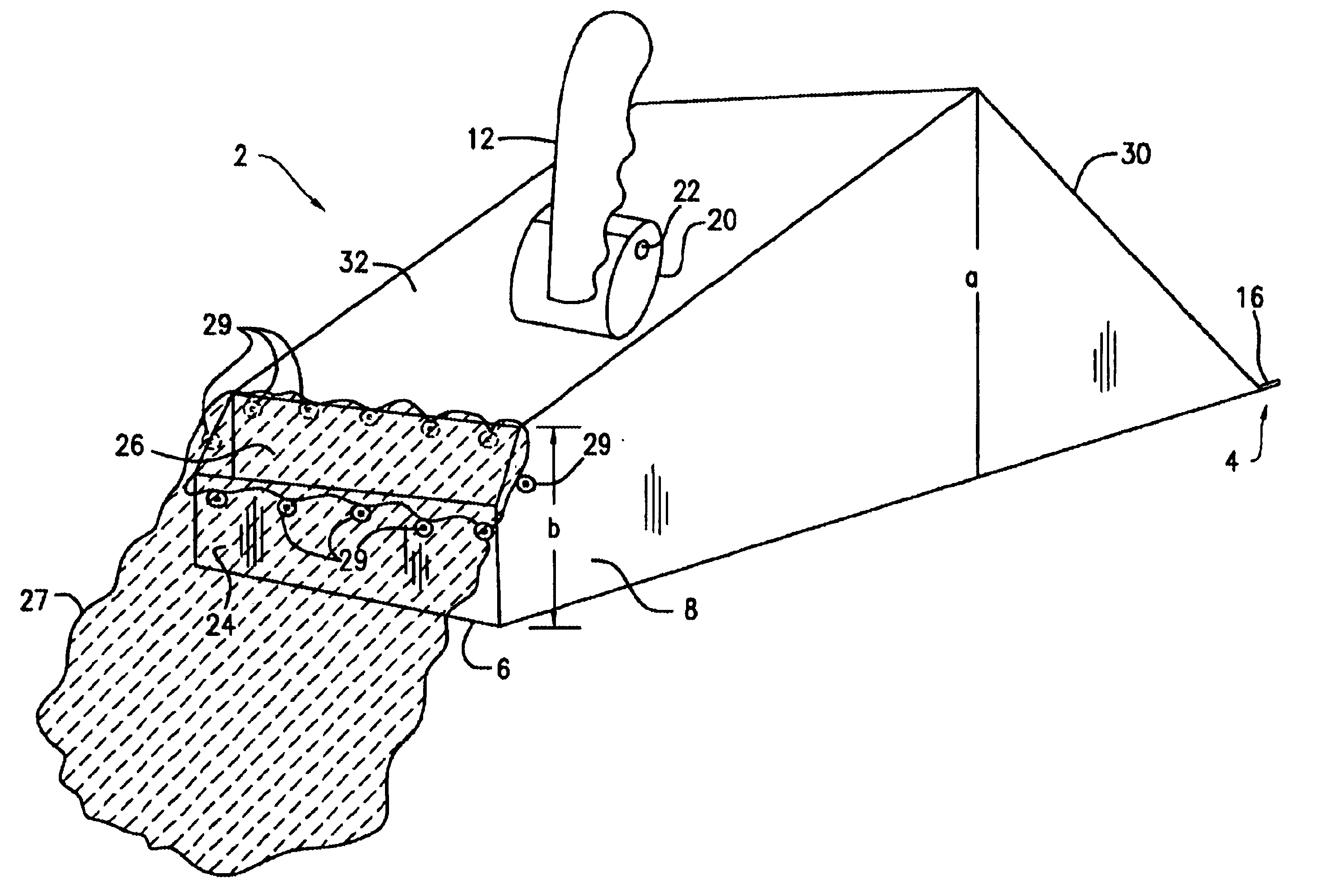
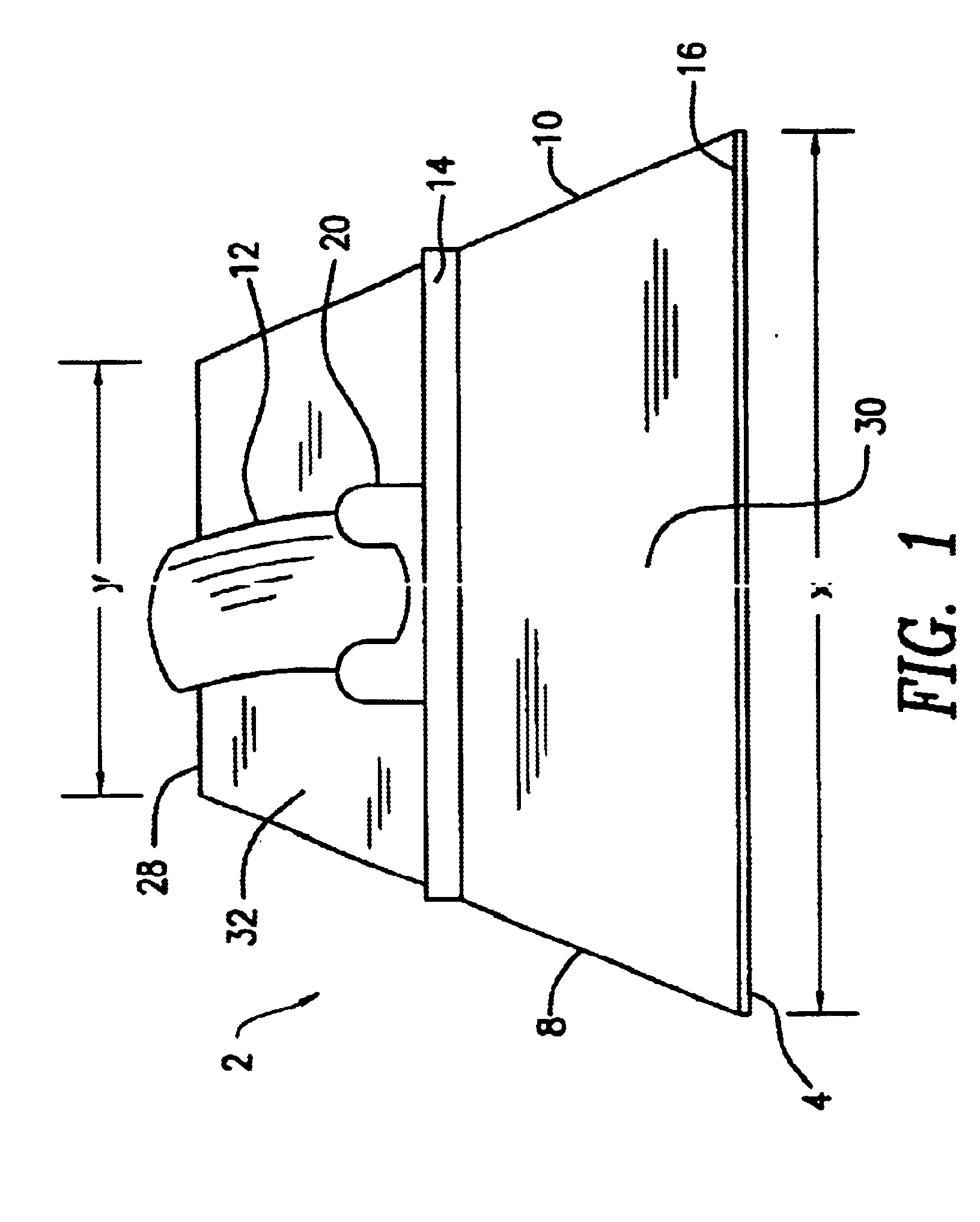
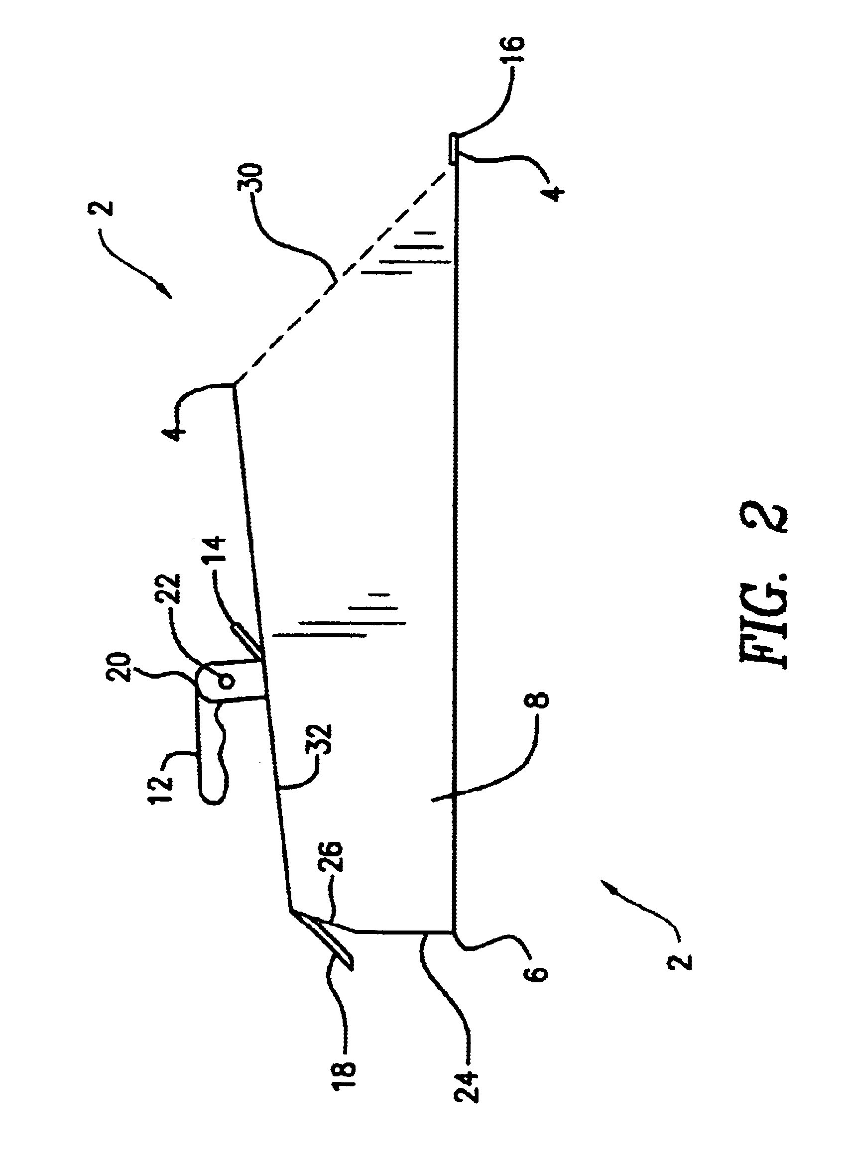
Referring to FIGS. 1-3, there is shown a preferred embodiment of a dust pan 2 of the present invention. The dust pan 2 has a front edge 4. In the preferred embodiment of FIGS. 1-3, the dust pan 2 is provided with a stiffener or break 16 along the front edge of the bottom panel. The inclusion of a stiffener 16 is not critical to the present invention, and a plain flat edge will suffice. The stiffener 16 provides improved stiffness to the edge.

The dust pan 2 also comprises two sides, 8 and 10, that may extend from the front edge 4 of the bottom panel to back panel 24. The top edges of the two sides 8 and 10 slope downwardly from front to rear, the sides 8 and 10 having a front edge a and a back edge b such that length a is greater than length b, as seen in FIG. 3. In preferred embodiments, a is at least about 10% greater than b, preferably at least about 25% greater, more preferably at least about 35% and most preferably at least about 40%. In all events, a is sufficiently greater tha...


PUM

PropertyMeasurementUnit
Lengthaaaaaaaaaa
Lengthaaaaaaaaaa
Lengthaaaaaaaaaa

Abstract

A dust pan for facilitating emptying of debris from the dust pan, that is nestable one within another for decreased shipping costs, and that can be easily and inexpensively manufactured as a single piece.

Description

FIELD OF THE PRESENT INVENTIONThe present invention relates to an improved dust pan. More particularly, the present invention relates to a dust pan that provides improved means for removing the debris from the dust pan, that has low transport cost due to nestability, and that can be injection molded in a single pieceBACKGROUND OF THE PRESENT INVENTIONDust pans of numerous shapes and sizes are known in the art. Dust pans are useful for cleaning in and about the home and commercial and industrial buildings. Dust pans typically have a broad shallow container or scoop attached to a handle, the scoop or container being open on one edge. The scoop is rested on the ground and a broom or other implement is used to push dust or other debris over the edge and into the scoop. The scoop is then manipulated like a shovel, to lift and dump the debris into a receptacle out of the same open end through which the debris or dust originally entered. Exemplary dust pan devices of the prior art include ...

Claims


Application Information

Patent Timeline
IPC IPC(8): A47L13/10A47L13/52
CPCA47L13/52
Inventor MEAD, RAYMOND
Owner MEAD RAYMIND AARON
Why Eureka
Try Eureka