Container end closure with an integral fluid channel

a container end and fluid channel technology, applied in the field of container end closures, can solve the problems of affecting the use of juice, the possibility of dirty container end closures, and the likelihood of moats collecting dirt, so as to achieve the effect of easily and effectively bringing fresh juice into the container

Active Publication Date: 2016-02-25
BALL CORP
View PDF2 Cites 1 Cited by
  • Summary
  • Abstract
  • Description
  • Claims
  • Application Information

AI Technical Summary

Benefits of technology

[0005]These and other needs are addressed by the various embodiments and configurations of the present invention. This invention relates to a novel system, device, and methods for providing a food and beverage container end closure with a luge, basin, channel, and / or tab for juice collection and distribution into the container. Note that the terms “basin,”“catch basin,” and “collection area” can be used interchangeably herein and the terms “collection area,”“channel,”“groove,” and “luge” can be used interchangeably herein. A “luge,” as used herein, is a channel, groove, or trough that is typically lower than the surrounding surface and directs fluids and solids to a predetermined location. The novel end closure provided herein allows the user to easily and effectively get fresh juice into the container.
[0007]Thus, it is one aspect of various embodiments of the present invention to provide an end closure that assists in the collection and distribution of juice into the container. A further aspect of various embodiments of the present invention is to provide a metallic end closure with a tab, basin, channel, and / or luge that assists in the collection and distribution of juice into the container.
[0008]One aspect of various embodiments of the present invention is to provide an end closure that directs freshly squeezed juice into the container contents. One advantage of some embodiments is that less fruit juice is spilled on the user and / or surrounding areas when the user squeezes juice onto the end closure of the container. Additionally, more juice ends up in the container rather than on the user, on surrounding areas, or in the moat formed by the countersink. Thus, embodiments of the present invention are less messy and less sticky due to the reduced juice spillage.
[0010]One aspect of some embodiments of the present invention is to provide a container end closure that safely enables a user to squeeze juice into the container. Thus, the end closure of the present invention reduces the likelihood a user will cut himself on the sharp edges of the pour opening while trying to get juice, fruit, etc. into the container.

Problems solved by technology

Multiple problems with these methods exist.
First, juice is often spilled on the user or on areas surrounding the container, such as tables and chairs.
Second, only a portion of the juice makes it into the container through the pour opening because juice is often spilled on the container end closure, or on the user, and eventually ends up in the moat area formed by the countersink of the end closure.
Third, container end closures may have the opportunity to become dirty during transportation with the moat area having a higher likelihood of collecting dirt.
Lastly, the size of the pour opening may prohibit adding the fruit or other material to container contents all together.

Method used


Image

  • Container end closure with an integral fluid channel
  • Container end closure with an integral fluid channel
  • Container end closure with an integral fluid channel

Examples


second embodiment

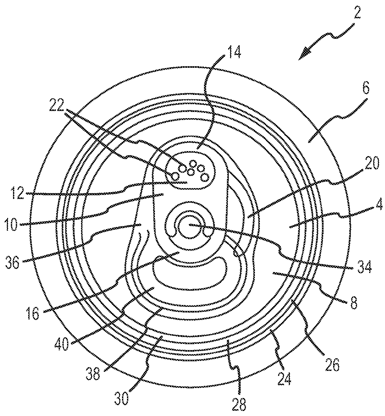
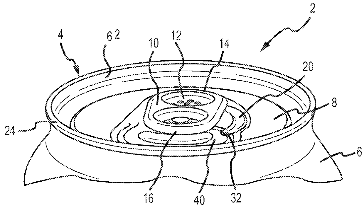
[0051]FIG. 4 is a top plan view of a container 2 with an end closure 4 double seamed 24 to a container body 6. The end closure 4 shown is the present invention and includes cut VI-VI. FIGS. 6A-6F depict numerous cross-sectional views taken at cut VI-VI showing embodiments VI-VI-A to VI-VI-F of end closures according to various embodiments. The end closure 4 comprises a chuck wall 26 interconnected to a countersink 28. The end closure 4 also comprises a panel radius 30 interconnected to a perimeter edge of a center panel 8 having a substantially flat portion and a pull tab 10 interconnected to the center panel 8 at an interconnection point or rivet 34.

[0052]The tab 10 has a nose 16 and a tail 14. In one embodiment, the tab 10 has an embossed or debossed portion (also called the tab deboss area herein) 12 positioned between the interconnection point 34 and the tab tail 14. In various embodiments, the deboss area 12 of the tab 10 has one or more forms 22 or perforations. In one embodim...

third embodiment

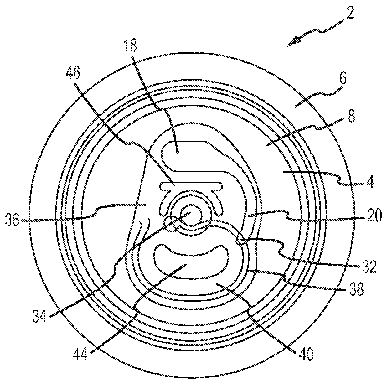
[0062]FIG. 6C shows the cross-section of the end closure of FIG. 4 at cut VI-VI. In this embodiment, the deboss area 36 is lower than the center panel 8. The deboss area 36 is positioned lower than the horizontal plane 48 defined by the upper surface of the center panel 8 a height H1, which is between about 0.023 inches and about 0.014 inches. However, the floor of the juice luge 20 and / or catch basin 18 is higher than the floor of the deboss 36 and higher than the floor of the center panel 8. The catch basin 18 and / or juice luge 20 are positioned above than a horizontal plane 48 defined by the upper surface of the center panel 8 a height H2, which is between about 0.030 inches and about 0.001 inches. Additionally, one raised portion 50A, 50B is positioned on either side of the luge 20 and / or catch basin 18. The raised portions 50A, 50B are taller than the center panel 8, deboss 36, and luge 20 and / or catch basin 18. The first raised portion 50A is positioned above than the horizont...

fifth embodiment

[0064]FIG. 6E the cross-section of the end closure of FIG. 4 at cut VI-VI. In this embodiment, the deboss area 36 and the juice luge 20 and / or catch basin 18 are lower than the center panel 8. Further, the deboss area 36 is lower than the juice luge 20 and / or catch basin 18. Additionally, one raised portion 50A, 50B is positioned on either side of the luge 20 and / or catch basin 18. The raised portions 50A, 50B are taller than the center panel 8, deboss 36, and luge 20 and / or catch basin 18. In alternate embodiments, the raised portions 50A, 50B can be the same height as the center panel 8. Here, the center panel 8 is positioned above a horizontal plane 54 defined by the bottom surface of the catch basin 18 and / or luge 20 a height H5, which is between about 0.011 inches and about 0.001 inches. The first raised portion 50A is positioned above than the horizontal plane 54 defined by the bottom surface of the catch basin 18 and / or luge 20 a height H6, which is between about 0.035 inches...


PUM


Abstract

An end closure for food and beverage containers is provided that comprises a novel center panel for collecting and distributing fluids and solids into a pour opening of the end closure. The fluids and solids may be juice and fruit or vegetable pieces. The end closure may further comprise a novel pull tab for assisting in the collection and distribution of the fluids and solids into the pour opening of the end closure. In one embodiment, the center panel comprises a catch basin and a luge for collecting and directing fluids and solids into the pour opening.

Description

CROSS-REFERENCE TO RELATED APPLICATION[0001]This application claims priority to U.S. Provisional Patent Application Ser. No. 62 / 039,830, filed Aug. 20, 2014. This application also claims priority to U.S. Provisional Patent Application Ser. No. 62 / 050,260, filed Sep. 15, 2014, the entire disclosures of which are incorporated by reference herein.FIELD OF THE INVENTION[0002]Embodiments of the present invention generally relate to containers and container end closures. More specifically, embodiments of the present invention relate to metallic beverage container end closures with tabs, basins, channels, and / or luges for collecting fluids and solids and distributing the fluids and solids into the container.BACKGROUND OF THE INVENTION[0003]Containers, and more specifically metallic beverage containers, generally contain an end closure with a pull tab or other form of stay on tab (“SOT”) to sever a score and form a pour opening. Users often like to add items to their beverages such as ice, ...

Claims


Application Information

Patent Timeline
Patent Type & Authority Applications(United States)
IPC IPC(8): B65D17/00A23L2/02
CPCB65D17/165A23L2/02A23V2002/00B65D2517/0077B65D2517/0014B65D2517/0056B65D2517/0076B65D2517/0098A23L2/00B65D17/4012
Inventor GATEWOOD, ERIK E.JACOBER, MARK A.
Owner BALL CORP
Why Eureka
Try Eureka