Cutter head with skirt

a cutter head and skirt technology, applied in the field of cutter head with skirt, can solve the problems of increasing the time required for a given excavation depth, and the spillage also increases the time required, so as to improve the efficiency of dredging operations, reduce the risk of spillage, and reduce the effect of production cos

Pending Publication Date: 2021-03-25
IHC HOLLAND NV
View PDF72 Cites 0 Cited by
  • Summary
  • Abstract
  • Description
  • Claims
  • Application Information

AI Technical Summary

Benefits of technology

[0015]According to a further aspect of the invention, a method of forming a cutter head with skirts comprises obtaining a cutter head comprising a base ring, a hub, a plurality of arms extending between the base ring and the hub, and a plurality of cutting tools on the plurality of arms; and connecting a plurality of skirts to the cutter head to form closed channels between at least some of the plurality of arms and the hub from a distal end of the cutter head toward the base ring ending with a surface configured to be parallel to a backplate and leave an open channel between the backplate and each skirt. Such a method can form a cutter head that minimizes spillage and increases the efficiency of a dredging operation.
[0016]According to an embodiment, the step of connecting the plurality of skirts comprises welding the plurality of skirts to the plurality of arms and to the hub. Welding can provide an effective means of connecting the skirts after they have been manufactured separately. Manufacturing skirts separately can be a simpler method of manufacture, particularly when the skirt will have a complex shape and / or bend.
[0017]According to an embodiment, the plurality of skirts are integrally formed with the plurality of arms, and the step of connecting a plurality of skirts comprises connecting a plurality of skirts to the hub to form closed channels between at least some of the plurality of arms and the hub from a distal end of the cutter head toward the base ring ending with a surface configured to be parallel to a backplate and leaving an open channel between the backplate and each skirt. Forming the plurality of arms integrally with the plurality of skirts ensures a strong connection between the arms and skirts for cutting operations.
[0018]According to an embodiment, the method further comprises connecting a plurality of cutting tools to the plurality of arms. Connecting cutting tools to the plurality of arms can ensure that the cutter head is able to effectively cut a bed, particularly when that bed is hard.
[0019]According to an embodiment, the step of connecting a plurality of skirts to the cutter head comprises connecting a skirt to form closed channels between each of the plurality of arms and the hub. Connecting a skirt to each arm to form a closed channel between each of the arms can ensure a very high resistance to spillage during a dredging operation with the cutter head.
[0020]According to a further aspect of the invention, a skirt for a cutter head comprises a rigid body configured to connect between an arm and a hub of a cutter head and extend from the distal end toward a backplate. Such a skirt can be connected to an existing cutter head to increase the resistance of spillage of such a cutter head.

Problems solved by technology

Spill also increases the time required for a given excavation depth as the spilled material needs to be removed by additional sweeps.

Method used


Image

  • Cutter head with skirt
  • Cutter head with skirt
  • Cutter head with skirt

Examples


Embodiment Construction

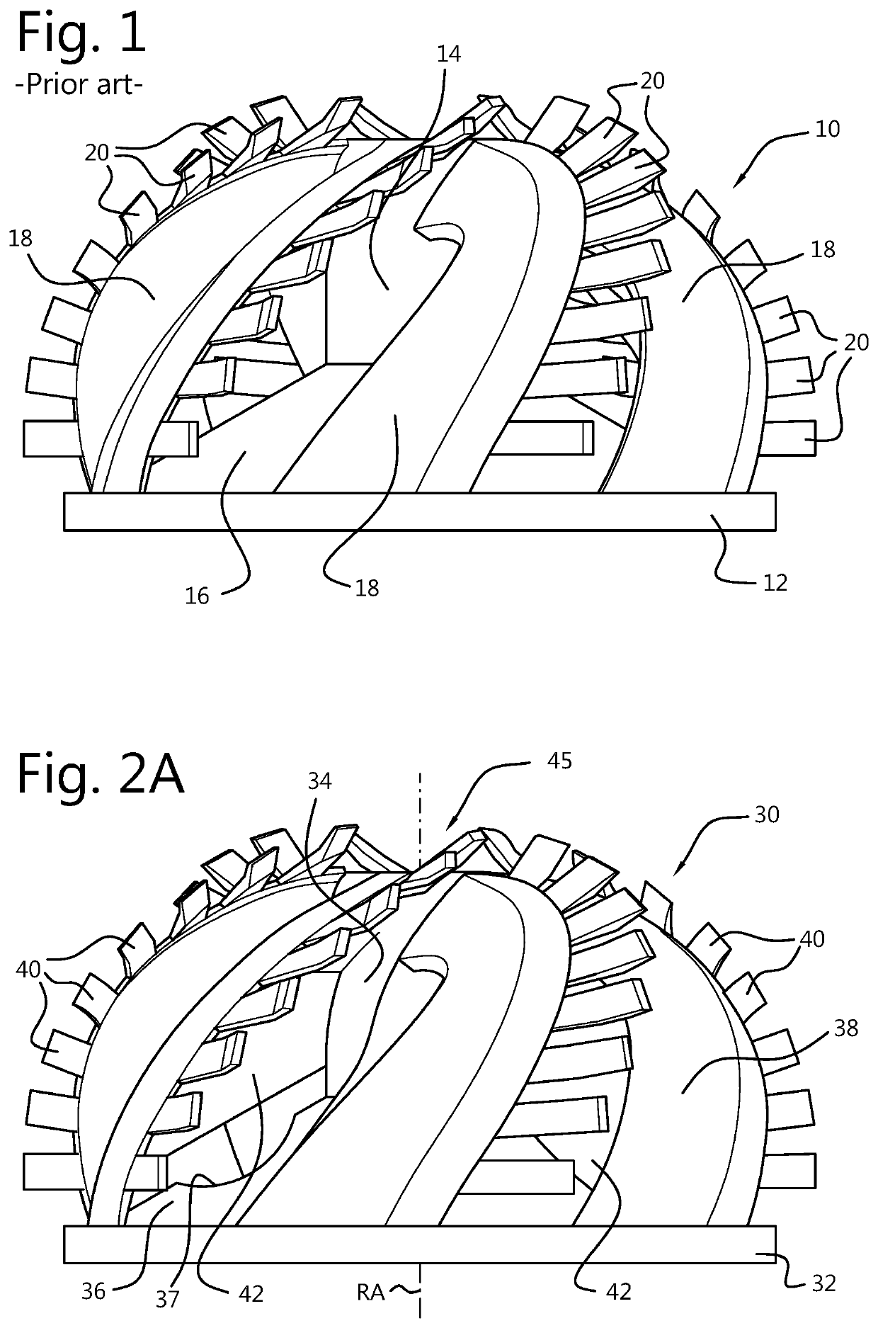
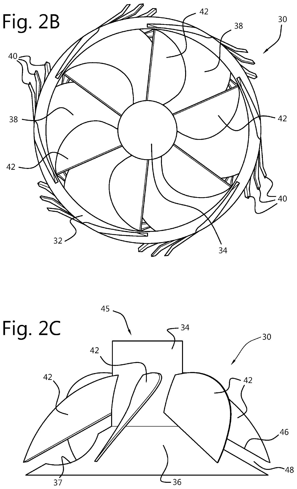
[0028]FIG. 2A shows a side view of a cutter head 30, with base ring 32, hub 34, backplate 36 with suction opening 37, arms 38, cutting tools 40 and spill skirts 42. FIG. 2B shows a back view of cutter head 30, with backplate 36 removed, and FIG. 2C shows a side view of cutter head 30, with arms 38 and base ring 32 removed.

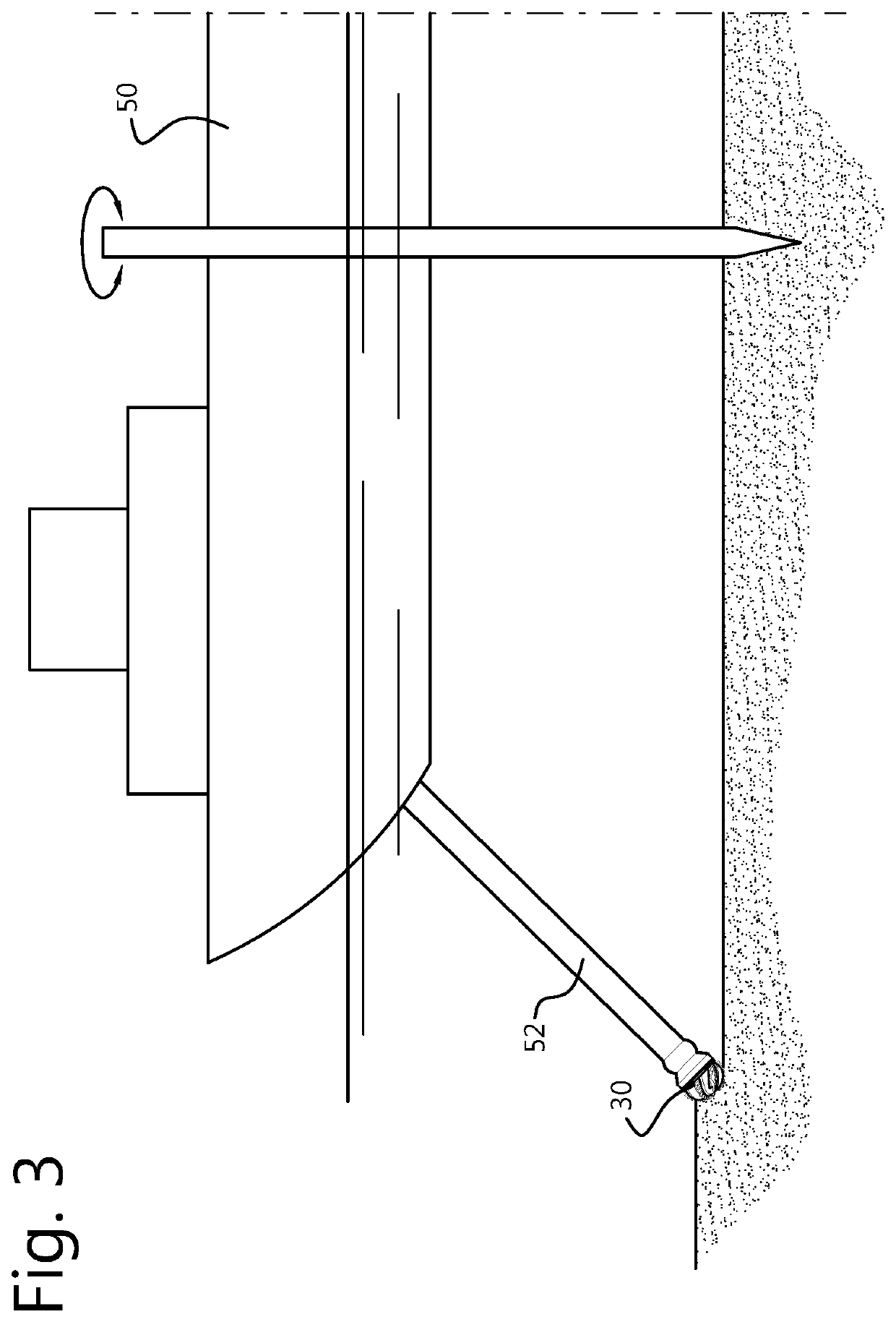
[0029]Arms 38 extend between base ring 32 and hub 34. Cutting tools 40 extend from arms 38 and can be formed integral or can be attached. Cutting tools 40 can take many different forms. Backplate 36 connects to a stationary part, for example, a ladder (see FIG. 3).

[0030]Spill skirts 42 each connect to hub 34 and to one arm 38, extending from distal end 45 toward base ring 32 to form a closed surface between arms 38 and hub 34. This forms closed channels between adjacent arms 38 with spill skirts 42. Spill skirts 42 end with a side 46 parallel to back plate 36, and leaving an opening 48 between skirt 42 and backplate 36. These openings 48 form a channel between skir...


PUM

PropertyMeasurementUnit
axis of rotationaaaaaaaaaa
pitch angleaaaaaaaaaa
lengthaaaaaaaaaa

Abstract

A cutter head arranged to rotate about an axis of rotation for removing material from a water bed comprises a base ring positioned respect to the axis of rotation; a hub positioned with respect to the axis of rotation; a plurality of arms extending between the base ring and the hub, the arms comprising a plurality of cutting tools; and a plurality of skirts, each skirt extending from one of the plurality of arms to the hub to form a closed surface between the arm and the hub from a distal end of the cutter head toward the base ring and ending with a side configured to be parallel to a backplate, leaving an open channel between the skirt and the backplate.

Description

BACKGROUND[0001]Cutter-suction dredgers (“CSD”) are vessels which can be used to cut and loosen material which is at least partly underwater. This cut material can then be sucked into a suction tube. CSD's are often used to cut hard surface materials, such as rock, although they may also be used to excavate gravel or sand.[0002]CSD's typically use a suction tube with a cutter head at the suction inlet. The cutter head may be connected to the dredger with a hub that is mounted on an axis with a drive to rotate the cutter head. The axis of rotation is referred to as the axial direction of the cutter head. The cutter head and suction inlet may be moveable with respect to the water bed being dredged. In order to draw the material into the suction tube, a wear-resistant pump may be provided, for example, a centrifugal pump. The material cut by the cutter head that has been drawn into the suction tube may then be transported away from the CSD, for example, by a floating pipe line to a dum...

Claims


Application Information

Patent Timeline
Patent Type & Authority Applications(United States)
IPC IPC(8): E02F3/92E02F3/88B23K31/02
CPCE02F3/9275B23K31/025E02F3/9293E02F3/8841E02F3/9231
Inventor MUNTS, EDWIN ALBERT
Owner IHC HOLLAND NV
Why Eureka
Try Eureka