Eureka AIR delivers breakthrough ideas for toughest innovation challenges, trusted by R&D personnel around the world.

Gutter guard

a gutter and frame technology, applied in the field of gutter frame, can solve the problems of affecting the free flow of water along the interior of the gutter,

Inactive Publication Date: 2004-02-17
STELMACH JOHN J
View PDF22 Cites 10 Cited by
  • Summary
  • Abstract
  • Description
  • Claims
  • Application Information

AI Technical Summary

Benefits of technology

"The present invention provides a gutter guard framework that is attached to the building fascia at a level substantially even with the upper edge of the gutter, without interfering with the normal function of the gutter. The framework uses restraining spurs to prevent sideways slippage of the ladder when it is in place. It also prevents the ladder from falling backwards away from the building while its occupant is in position on the ladder or ascending or descending the roof area. The framework also provides means for locking the ladder in place, to prevent theft of the ladder in the event the workman finds it necessary to leave the ladder unattended for a period of time. The invention also includes ladder locator means for marking the spot or spots which have been designated for safe access to the roof."

Problems solved by technology

Because of the relative weakness of the construction of a gutter, the weight of the ladder and of the person ascending such ladder create a risk of damaging the gutter.
Further, because the relatively narrow surfaces of the rails of the ladder rest against the relatively narrow, horizontally extending surface of the outer edge of the gutter, the person ascending the ladder faces the risk of ladder slippage and a consequently serious fall.
However, in such arrangements the guard apparatus occupies a considerably lower portion of the inner channel of the gutter and thus interferes with the free flow of water, leaves and other debris along the interior of the gutter.

Method used


Image

  • Gutter guard
  • Gutter guard
  • Gutter guard

Examples


Embodiment Construction

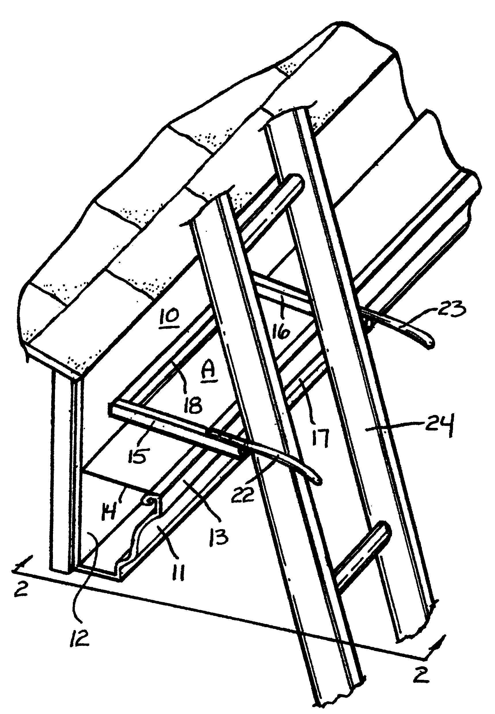
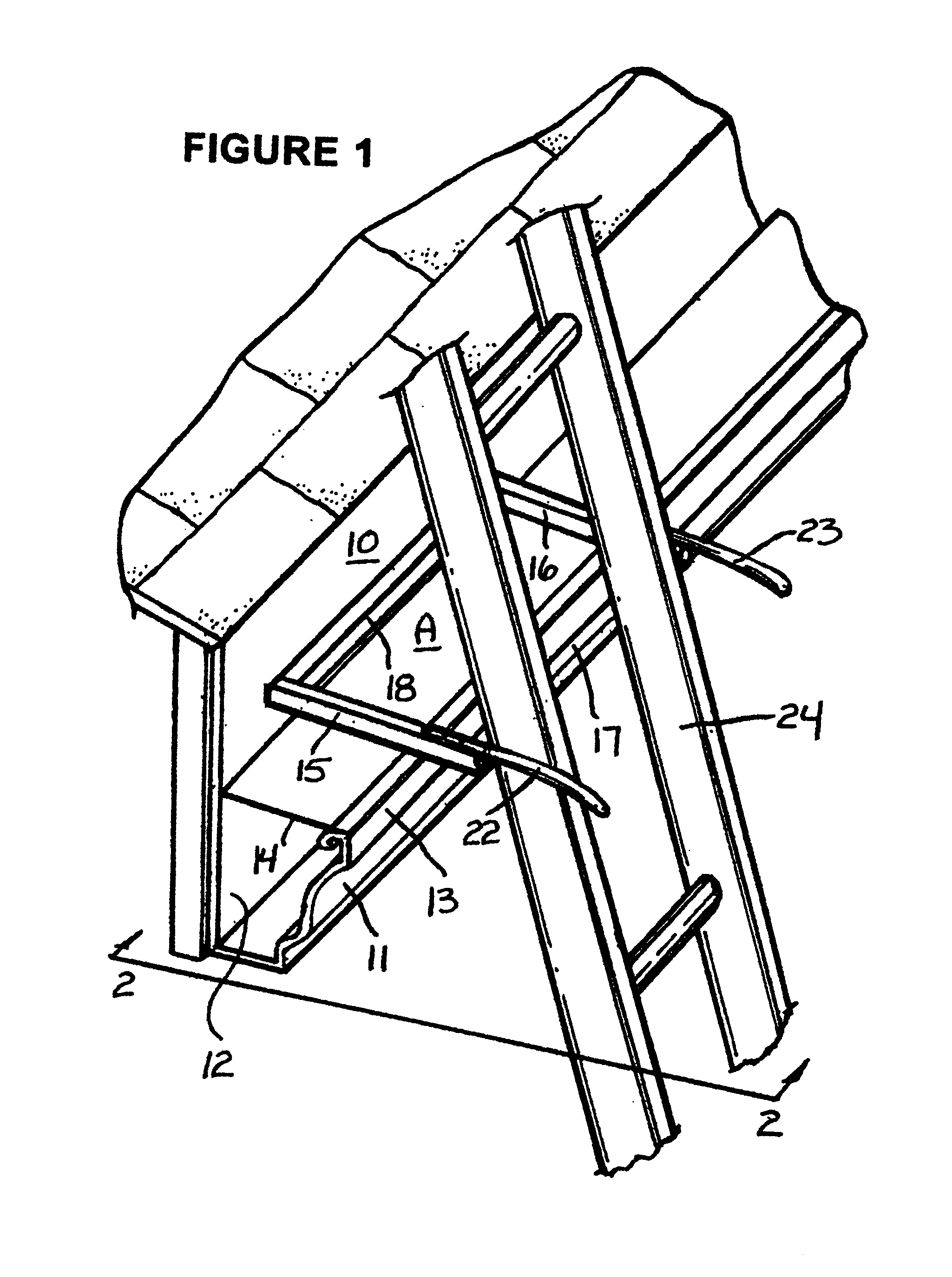
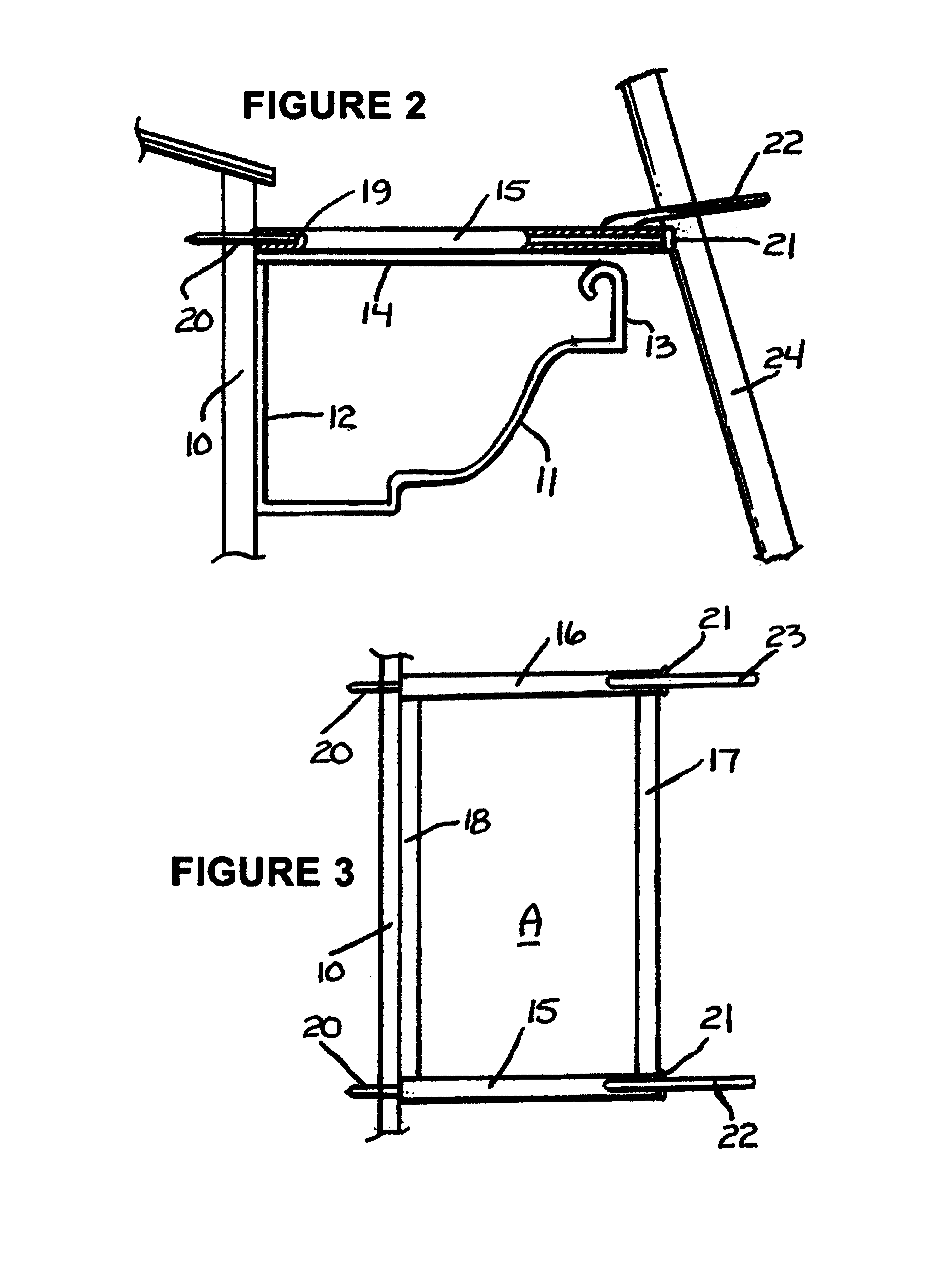
As illustrated in FIGS. 1 and 3, the invention is based on the use of a gutter guard frame generally indicated by the letter A. The frame A is attached to a fascia board 10 above the top of a gutter 11 that is also attached to the fascia board 10. As shown, the gutter has a back side 12 that is attached to the fascia board 10, a front side 13, and an open top, the horizontal plane of which is indicated by the numeral 14. The gutter guard frame A is made up of a pair of side legs 15 and 16, which are connected by a front leg 17. The frame A may also have a back leg 18, which is not an essential element, but which is preferred for reinforcement purposes. As shown in FIGS. 2 and 3, each of side legs 15 and 16 is a hollow tube providing a longitudinal passageway 19 through which a spike 20, having a head 21, is driven into the fascia board 10 to attach each of the side legs 15 and 16 to the fascia board. Instead of a spike, the element 20 may also be a long screw, which may be screwed i...


PUM


Abstract

A combination gutter protector and safety device for use with a ladder which is leaned against the upper part of a structural wall that is equipped with a rain gutter under the eaves. The device is secured to the fascia board of the wall in a longitudinal plane adjacent to or substantially even with the plane of the open top of the gutter in such position that it protects the gutter against deformation when the ladder is put in place. The device also serves to provide a contained recess for holding the ladder against slippage and, if desired, locking the ladder against theft. The structure of the device accomplishes the above purposes without occupying any part of the channel of the gutter and thus does not interfere with the free flow of water, leaves and other debris in the channel of the gutter.

Description

This invention relates to an improved device for supporting a ladder against a building structure, and more particularly to an improved ladder support which is mounted on the fascia board of a structure to prevent gutter deformation from contact by the ladder.When a person desires to reach the roof of a house, the usual procedure is to place a ladder in position against the wall or an eave of the roof. If a rain gutter is in place below the eave, the ladder is usually placed against the gutter. Because of the relative weakness of the construction of a gutter, the weight of the ladder and of the person ascending such ladder create a risk of damaging the gutter. Further, because the relatively narrow surfaces of the rails of the ladder rest against the relatively narrow, horizontally extending surface of the outer edge of the gutter, the person ascending the ladder faces the risk of ladder slippage and a consequently serious fall. Accordingly, there exists in the art a need for a gutt...

Claims


Application Information

Patent Timeline
Patent Type & Authority Patents(United States)
IPC IPC(8): E06C1/34E06C7/48E06C1/00E06C7/00
CPCE06C1/34E06C7/486
Inventor STELMACH, JOHN J.
Owner STELMACH JOHN J
Why Eureka
Eureka Blog
Learn More