Electrical connector with operation lever positioning configuration

a technology of positioning configuration and operation lever, which is applied in the direction of coupling contact members, electrical apparatus construction details, coupling device connections, etc., can solve the problems of operation lever being prone to be accidentally over-rotated beyond said perpendicular position, cpu socket damage,

Inactive Publication Date: 2004-03-02
HON HAI PRECISION IND CO LTD
View PDF6 Cites 5 Cited by
  • Summary
  • Abstract
  • Description
  • Claims
  • Application Information

AI Technical Summary

Benefits of technology

The actuation device comprises a camshaft and an operation lever. The camshaft is rotatably positioned between the base and the cover, and defines a locating recess therein. The operation lever extends perpendicularly from one end of the camshaft and is positioned substantially outside the base and the cover, to facilitate manual handling by a user. The base comprises a main portion, and a front portion integrally extending from the main portion. The main portion defines a multiplicity of receiving passageways arranged in a rectangular array. Each passageway receives an electrical terminal therein, and the electrical terminals are electrically connected with the PCB. The front portion defines an engaging surface for engaging with the cover. A locating slot is defined at the engaging surface, rotatably locating the camshaft of the actuation device therein. The front portion forms a locating block in the slot. The locating block engages with the camshaft at the locating recess, to help prevent the operation lever from being over-rotated in either of opposite directions.

Problems solved by technology

In this process, the operation lever is prone to be accidentally over-rotated beyond said perpendicular position.
When this happens, the CPU socket may be damaged.
In this process, the operation lever is prone to be accidentally over-rotated beyond said parallel position.
When this happens, the CPU socket may be damaged.

Method used


Image

  • Electrical connector with operation lever positioning configuration
  • Electrical connector with operation lever positioning configuration
  • Electrical connector with operation lever positioning configuration

Examples


Embodiment Construction

Reference will now be made to the drawings to describe the present invention in detail.

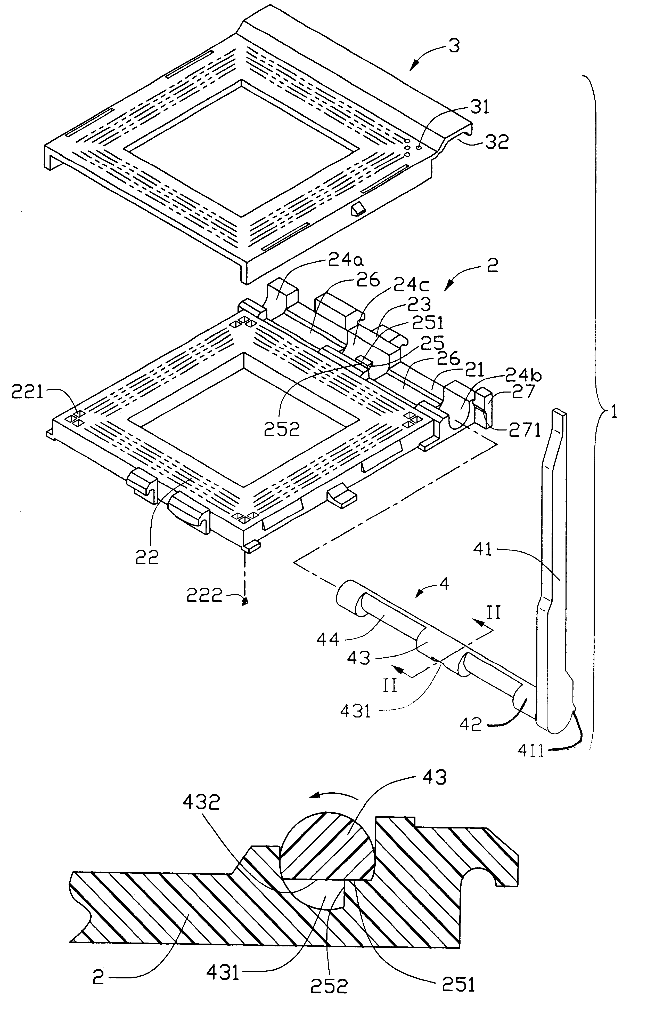
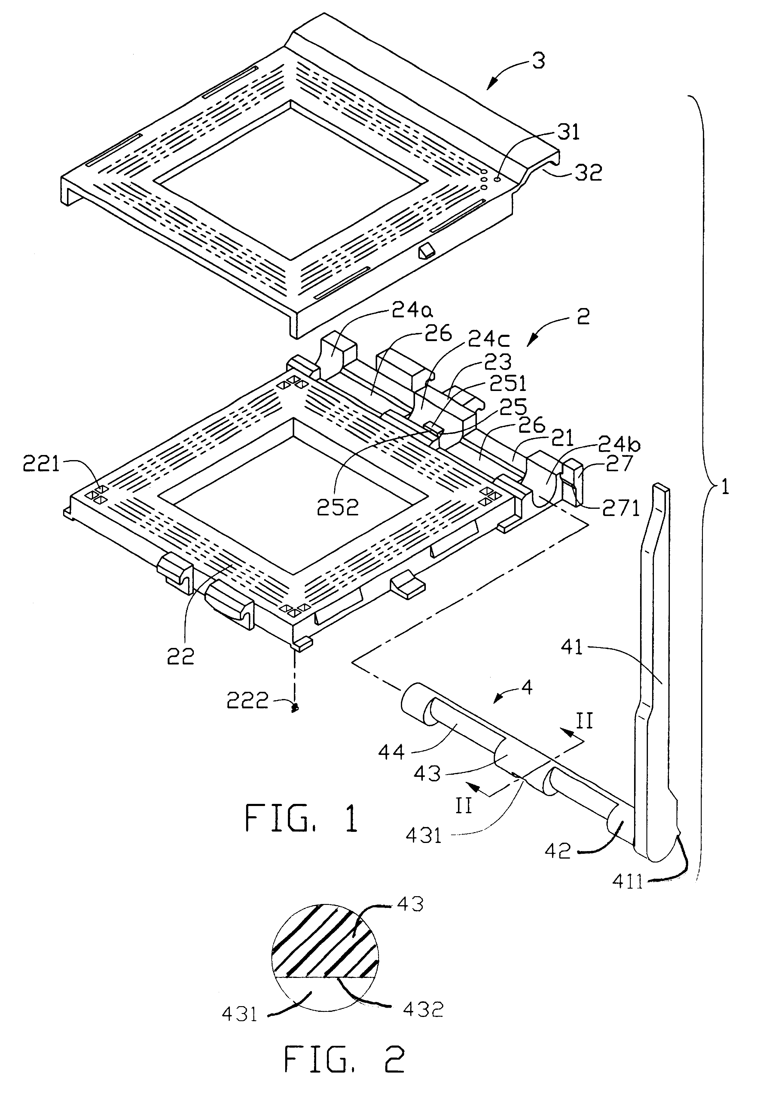
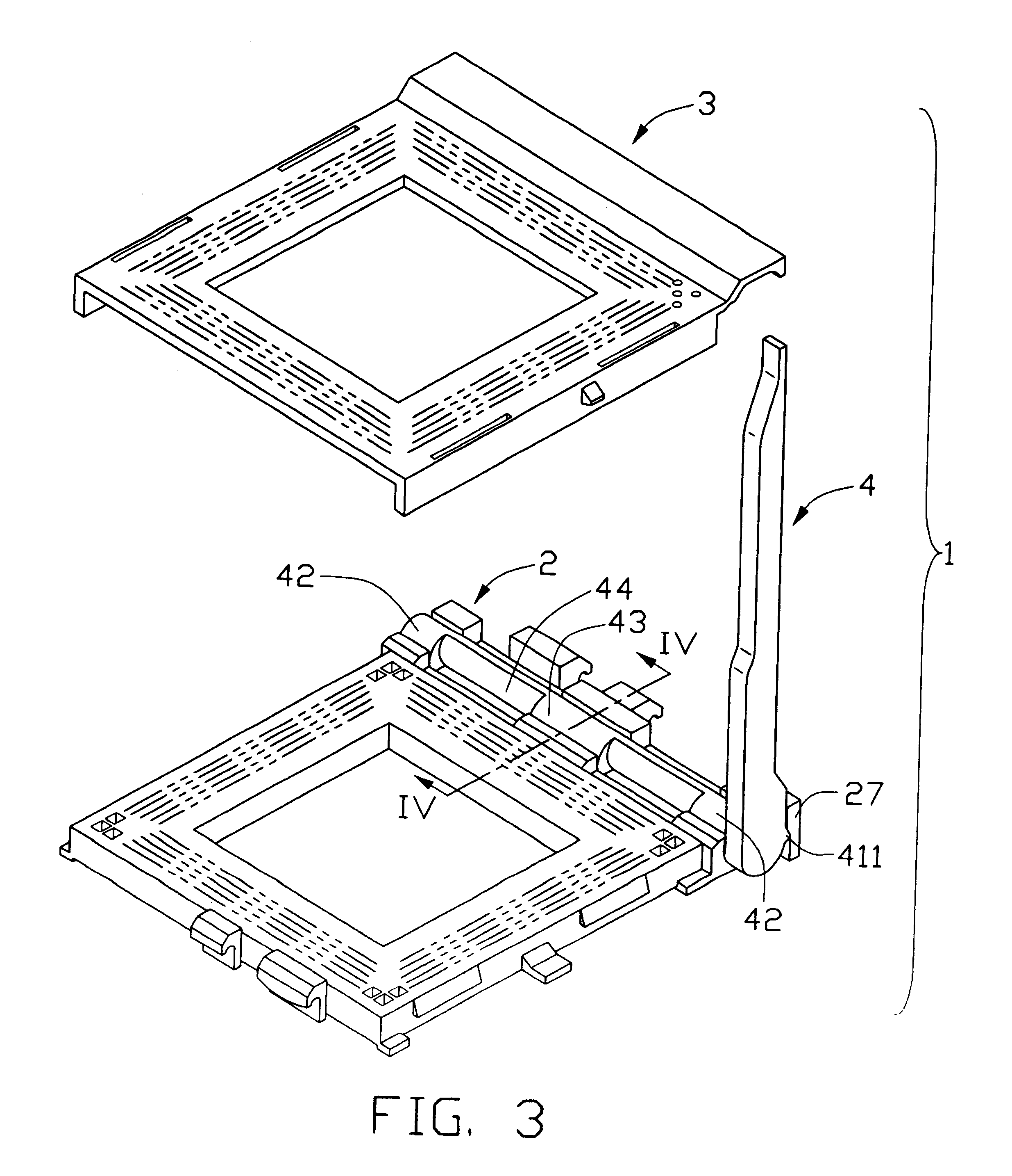
Referring to FIGS. 1 and 2, an electrical connector 1 in accordance with a preferred embodiment of the present invention is for electrically connecting a CPU (not shown) to a PCB (not shown). The electrical connector 1 comprises a generally rectangular insulative base 2, a cover 3 slidably attached on the base 2, and an actuation device 4 positioned between the base 2 and the cover 3 for actuating the cover 3 to slide along the base 2.

The actuation device 4 comprises a camshaft positioned between the base 2 and the cover 3, and an operation lever 41. The operation lever 41 extends perpendicularly from one end of the camshaft, and is positioned substantially outside the base 2 and the cover 3 to facilitate manual handling by a user. The camshaft comprises a pair of supporting portions 42 at opposite ends thereof, a pair of actuating portions 44 adjacent the supporting portions 42, and a central loc...


PUM


Abstract

An electrical connector (1) for electrically connecting an electronic package with a circuit substrate. The connector includes a base (2), a cover (3) slidably attached on the base, and an actuation device (4) for actuating the cover to slide along the base. The actuation device includes a camshaft and an operation lever (41). The camshaft is rotatably positioned between the base and the cover, and defines a locating recess (431) therein. The base includes a main portion (22) and a front portion (21). The front portion defines an engaging surface (23) for engaging with the cover. A locating slot is defined at the engaging surface, rotatably locating the camshaft of the actuation device therein. The front portion forms a locating block (25) in the slot. The locating block engages with the camshaft at the locating recess, to help prevent the operation lever from being over-rotated in either of opposite directions.

Description

1. Field of the InventionThe present invention relates to an electrical connector for electrically connecting an electronic package such as a central processing unit (CPU) with a circuit substrate such as a printed circuit board (PCB), and particularly to an electrical connector having an operation lever accurately and safely positioned at respective limits of its range of movement.2. Description of Prior ArtElectrical connectors ate widely used in personal computer (PC) systems for electrically connecting electronic packages such as CPUs with circuit substrates such as PCBs. Typical such electrical connectors are known as CPU sockets. A typical CPU socket comprises a base soldered to and electrically connected with the PCB, a cover slidably mounted on the base and having a CPU attached thereon, and an actuation device for actuating the cover to slide along the base.The CPU has a multiplicity of pins depending from a bottom surface thereof and arranged in a rectangular array. The co...

Claims


Application Information

Patent Timeline
Patent Type & Authority Patents(United States)
IPC IPC(8): H05K7/10
CPCH05K7/1007
Inventor HE, WENYE, HUI
Owner HON HAI PRECISION IND CO LTD
Why Eureka
Try Eureka