Automatic clutch with manual override control mechanism

a control mechanism and automatic clutch technology, applied in the direction of clutches, chain/belt transmissions, vehicle components, etc., can solve the problems of not being able to mechanically engage the automatic clutch, not being able to bumpstart by popping,

Inactive Publication Date: 2004-03-16
DRUSSELL WILFLEY DESIGN LLC
View PDF24 Cites 29 Cited by
  • Summary
  • Abstract
  • Description
  • Claims
  • Application Information

AI Technical Summary

Benefits of technology

It is a further object of the present invention to provide for a novel and improved clutch-engaging mechanism which requires minimal movement of an activating member to effect engagement of the clutch plates of an automatic clutch and wherein the starting mechanism is conformable for use with different types of existing automatic clutch mechanisms.
It is a still further object of the present invention to provide a manual control for an automatic motorcycle clutch, either in the form of a push rod or pull rod, which enables the clutch to remain in a normally released position when at low speeds or idling and can effect manual clutch for bumpstarting.

Problems solved by technology

Previously, at least in the automatic clutch versions, it was not possible to bumpstart by popping or manually engaging the clutch after getting up to speed.
Nevertheless, no practical way has been devised previously to mechanically engage the automatic clutch for purposes of bumpstarting it in emergency situations.

Method used


Image

  • Automatic clutch with manual override control mechanism
  • Automatic clutch with manual override control mechanism
  • Automatic clutch with manual override control mechanism

Examples


Embodiment Construction

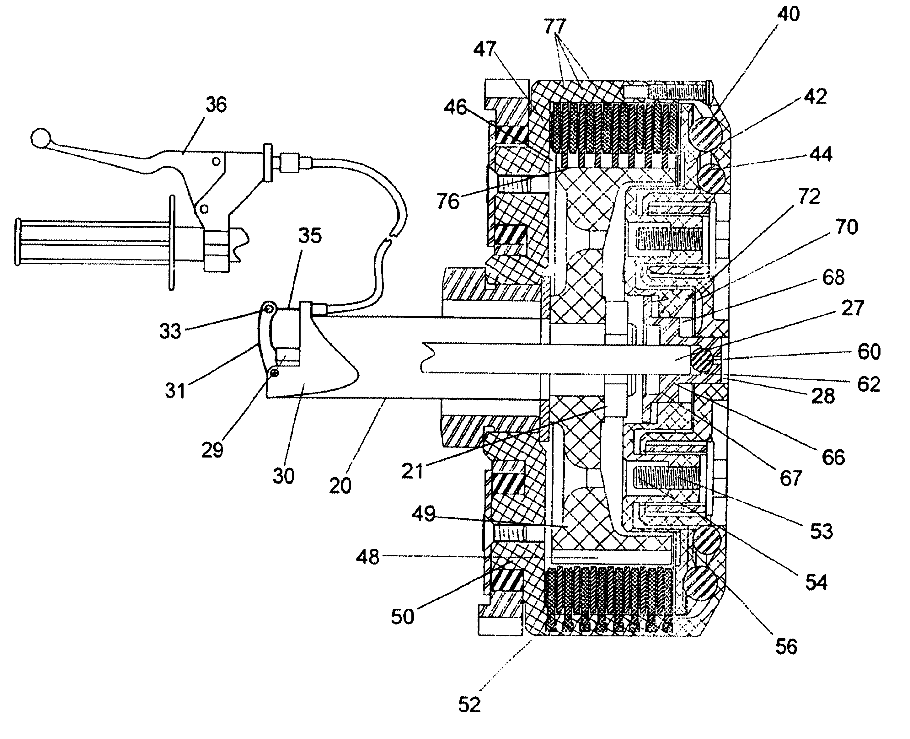
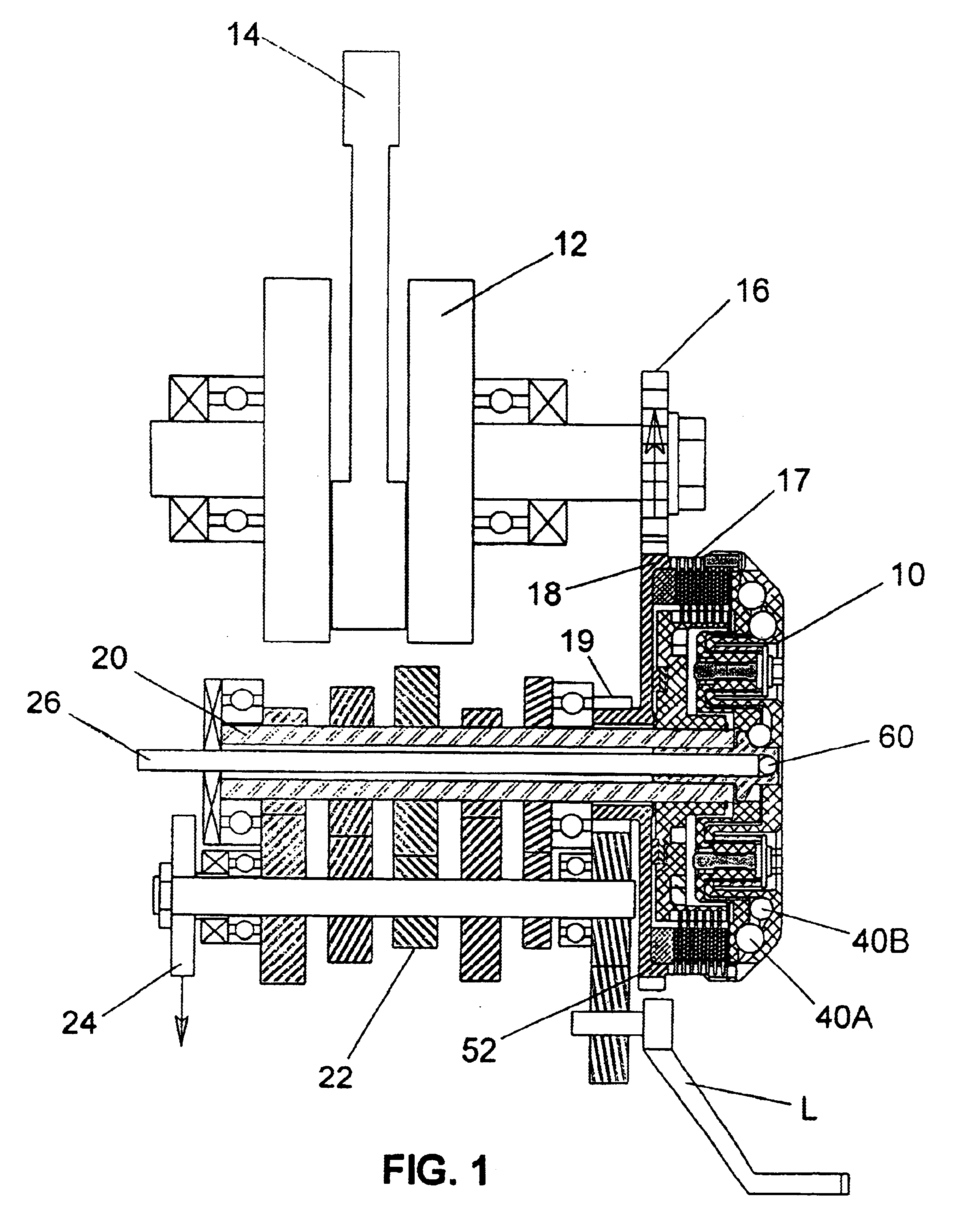
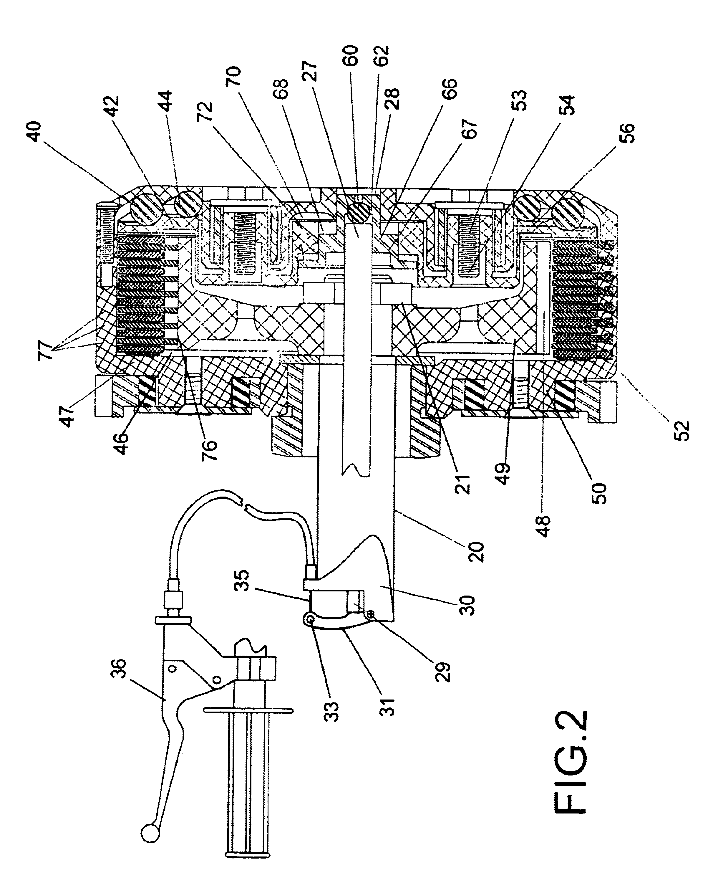
There is shown by way of illustrative example in FIG. 1 the mounting of a preferred form of automatic clutch assembly 10 in the drive train of an off-road motorcycle wherein a crankshaft set 12 from the engine piston 14 imparts rotation to the power input side of the clutch 10 through a pinion 16 into primary drive gear 18 on clutch housing 17. A transmission shaft 20 is mounted for rotation by the clutch 10 when in the engaged position and through speed reduction gears represented at 22 to rotate the drive sprocket 24 of a chain drive, not shown, into the rear wheel of the bike. In accordance with the present invention, a push rod 26 extends through the transmission shaft 20 to manually engage the clutch plates to be hereinafter described for the purpose of bumpstarting the engine. The foregoing description of the drive train is intended more as a setting for the present invention inasmuch as there are numerous types of drive trains for motorcycles with which the push rod of this i...


PUM


Abstract

An automatic clutch for automotive and other applications employs a control rod to manually control engagement and disengagement of the clutch independently of its speed of rotation, and in one form of invention can be employed in manual start motorcycles to engage the clutch for bumpstarting purposes before the engine is up to speed, and in an alternate form a control rod can be employed in electrically started bikes to lock the clutch against engagement whether or not the engine is up to the speed required for automatic engagement of the clutch. The control rod may either extend through the transmission shaft from one end of the clutch housing or may extend through the opposite end of the clutch housing, and in certain applications the hereinbefore described control rods can be combined to selectively control bumpstarting to manually effect clutch engagement or as a locking mechanism to prevent clutch engagement.

Description

BACKGROUND AND FIELD OF INVENTIONThis invention relates to automatic clutches adapted for use with a motive power source, and more particularly relates to a novel and improved automatic centrifugal clutch with a manual override control mechanism for motorcycles.Motorcycles employ internal combustion engines either of the two-stroke or four-stroke variety, the fuel being ignited by an electric starter to cause the pistons to advance through their respective cylinders and to turn the engine crankshaft via a connecting rod which joins the piston and crankshaft together. The crankshaft converts the up and down movement of the piston to a circular motion which operates through a gear or chain reduction to power a pinion into the primary drive gear on a clutch housing. This permits the rider to disconnect the engine from the transmission in order to shift from one gear to another. The clutch itself is operated by a hand lever so as to allow power to be fed gradually from the engine to the...

Claims


Application Information

Patent Timeline
Patent Type & Authority Patents(United States)
IPC IPC(8): F16D43/12F16D43/00F16D23/12
CPCF16D23/12F16D43/12
Inventor DRUSSEL, DOUGLAS W.WILFLEY, G. MICHAEL
Owner DRUSSELL WILFLEY DESIGN LLC
Why Eureka
Try Eureka