Rotary displacement machine having at least two annular displacement gears and supply channels

a technology of annular displacement and displacement gear, which is applied in the direction of rotary or oscillating piston engines, rotary piston engines, engine lubrication, etc., can solve the problems of limiting the efficiency and the application of machines, disturbing the vortices and cavitations of fluid flow, and the filling of the conveying chamber formed between the teeth of displacement gear wheels is not optimal,

Inactive Publication Date: 2004-03-16
SAGAWE JOHANN +1
View PDF16 Cites 14 Cited by
  • Summary
  • Abstract
  • Description
  • Claims
  • Application Information

AI Technical Summary

Problems solved by technology

Even though the known rotary displacement machines have been successfully used in practice for decades, at high rotary speeds problems result in regard to turbulences and cavitation which limit the efficiency and the applications of the machines and which have the effect that filling of the conveying chambers formed between the teeth of the displacement gear wheels is not optimal.
One basic problem are the displacement gear wheels provided in all of the aforementioned known rotary displacement machines because they must be supported in a complex way

Method used


Image

  • Rotary displacement machine having at least two annular displacement gears and supply channels
  • Rotary displacement machine having at least two annular displacement gears and supply channels
  • Rotary displacement machine having at least two annular displacement gears and supply channels

Examples


Embodiment Construction

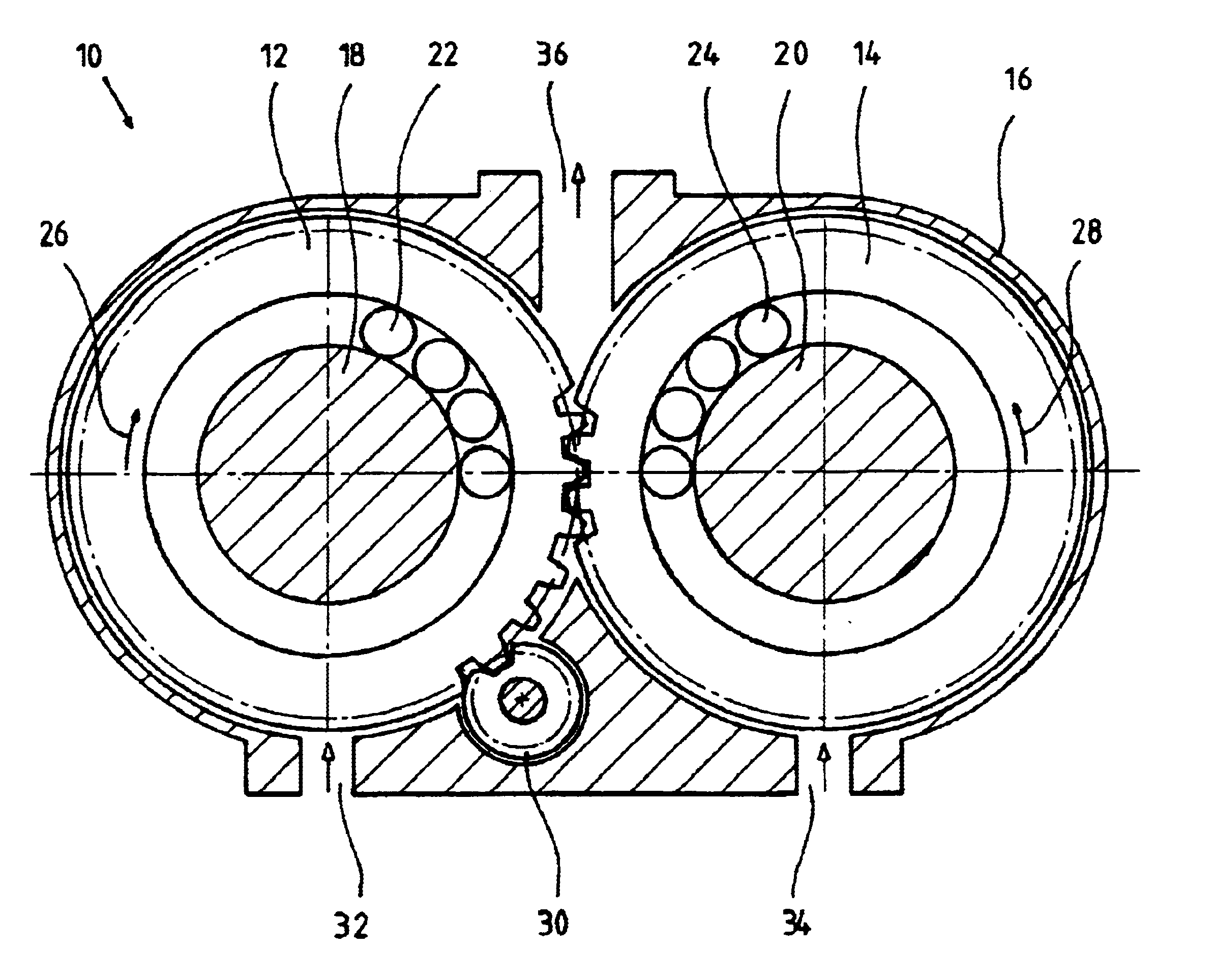
In FIG. 1, a rotary displacement machine, identified in its entirety at 10, is shown in which two displacement gear wheels configured as annular displacement gears 12 and 14 are arranged in a housing 16 such that they mesh within one area.

The annular displacement gears are supported to be rotatable about a stationary axle 18 or 20, respectively. The supporting action between axle and annular gear is realized by balls 22 and 24, respectively, wherein, for reasons of clarity, only a few balls are illustrated of which only one is identified by reference numeral, respectively.

As indicated by the arrows 26 and 28, upon proper operation of the rotary displacement machine 10 the annular displacement gear 12 to the left in the Figure rotates right-handed while the annular displacement gear 14 to the right in the Figure rotates left-handed.

For providing a driving action or output action of the annular displacement gears, a drive gear wheel 30 is provided in this embodiment which meshes with ...


PUM


Abstract

A rotary displacement machine has a housing and at least two annular displacement gears arranged in the housing and supported rotatably on a stationary axle, receptively. The at least two annular displacement gears have external teeth for conveying a fluid. At least two supply channels are provided in the housing and have a supply mouth, respectively, opening toward the annular displacement gears for supplying a fluid to the annular displacement gears. The supply mouth is configured such that, upon operation of the rotary, displacement machine, a fluid exiting from the supply mouth reaches either only the teeth of a single one of the annular displacement gears or only the teeth of the annular displacement gears rotating in the same direction.

Description

1. Field of the InventionThe invention relates to a rotary displacement machine with at least two displacement gear wheels with external teeth for conveying a fluid and with at least two supply channel with supply mouths in the area of the displacement gear wheels for supplying the fluid to the displacement gear wheels, wherein each one of the supply mouths is configured such that upon proper operation of the rotary displacement machine fluid exiting from the supply mouth can reach either only the teeth of a single displacement gear wheel or only the teeth of such displacement gear wheels which rotate in the same direction. The invention furthermore relates to a housing for such a machine.2. Description of the Related ArtRotary displacement machines of the aforementioned kind can be used as pumps, i.e., as pressure generators, as well as motors, i.e. pressure consumers. When the rotary displacement machine is used as a motor, the conveyed fluid is generally a hydraulic oil. When the...

Claims


Application Information

Patent Timeline
IPC IPC(8): F01C1/18F01C1/00F04C15/00F04C2/00F04C2/14F04C2/18F04C2/08
CPCF04C2/086F04C2/14F04C15/06
Inventor SAGAWE, JOHANNSAGAWE, GOTTFRIED
Owner SAGAWE JOHANN
Why Eureka
Try Eureka