Web monitoring

a web monitoring and web technology, applied in the field of web monitoring, can solve the problems of causing a belt temperature jump, and affecting the reliability of optical detection,

Inactive Publication Date: 2004-03-16
VOITH PATENT GMBH
View PDF6 Cites 4 Cited by
  • Summary
  • Abstract
  • Description
  • Claims
  • Application Information

AI Technical Summary

Benefits of technology

In order to increase the reliability of the measuring arrangement, the temperature measurement can take place at several locations along the run of the belt and / or at several locations crosswise to the belt travel direction. The arrangement of several temperature measuring locations crosswise to the belt travel direction also permits monitoring of individual zones of the fibrous material web, so that the transfer of the strip of the fibrous material web that is getting wider can be relatively precisely detected when starting the machine.
The temperature measurement should be accomplished without contact so as not to impair the belt or the fibrous material web. Temperature sensors in the form of IR sensors or IR thermography cameras are particularly suitable for this. In this connection, a cleaning element, preferably in the form of an air jet, and / or a cooling element, can be allocated to the temperature sensors. Both substantially increase the reliability of the measurement. The temperature sensors should feature a measuring area with a diameter between about 20 and 200 mm, preferably between about 20 and 100 mm.
If several temperature sensors are present for temperature monitoring of a larger area, in particular, crosswise to the belt travel direction, the distance between two temperature sensors should be between about 100 and 1000 mm, preferably between about 200 and 600 mm. The sensors can also be arranged at several particularly interesting locations, for example in the edge areas of the fibrous material web shortly before and / or after an airborne web dryer or drying hood or the like. In addition, it can also be an advantage if at least one temperature sensor is embodied to be traversable crosswise to the fibrous material web. The temperature can thus be detected via this temperature sensor at least over a portion of the width of the belt or the fibrous material web.
The use of the process and the device can also be accomplished advantageously in the area of a dryer section for drying the fibrous material web, whereby the belt is embodied as a drying screen. This provides a high degree of reliability of the process if before the temperature measurement the fibrous material web is heated by at least one heating element, preferably in the form of an IR radiator, a heated drying cylinder, hot-air jets or the like.
The result of the temperature measurement should be supplied to a control unit, which evaluates the temperature change. Here it is advantageous if the temperature of the belt outside the area touched by the fibrous material web is also measured for determining a temperature comparison value.
If the measurement of the temperature of the belt takes place after the transfer of the fibrous material web, this should occur as quickly as possible afterward, so as to minimize outside influences on the temperature as well as the reaction time. This measuring location offers particular advantages with respect to the spatial freedom of design.

Problems solved by technology

The reliability of the optical detection is impaired, however, by the contamination of the belts, the mostly warm, moist and contaminated air in the area of the machine as well as the contamination of the sensors or cameras.
In addition to the high price of the measuring units, their reliability is unsatisfactory.
Thus, in particular a tear in the fibrous material web produces a jump in the temperature of the belt.

Method used


Image

  • Web monitoring
  • Web monitoring

Examples


Embodiment Construction

The particulars shown herein are by way of example and for purposes of illustrative discussion of the embodiments of the present invention only and are presented in the cause of providing what is believed to be the most useful and readily understood description of the principles and conceptual aspects of the present invention. In this regard, no attempt is made to show structural details of the present invention in more detail than is necessary for the fundamental understanding of the present invention, the description taken with the drawings making apparent to those skilled in the art how the several forms of the present invention may be embodied in practice.

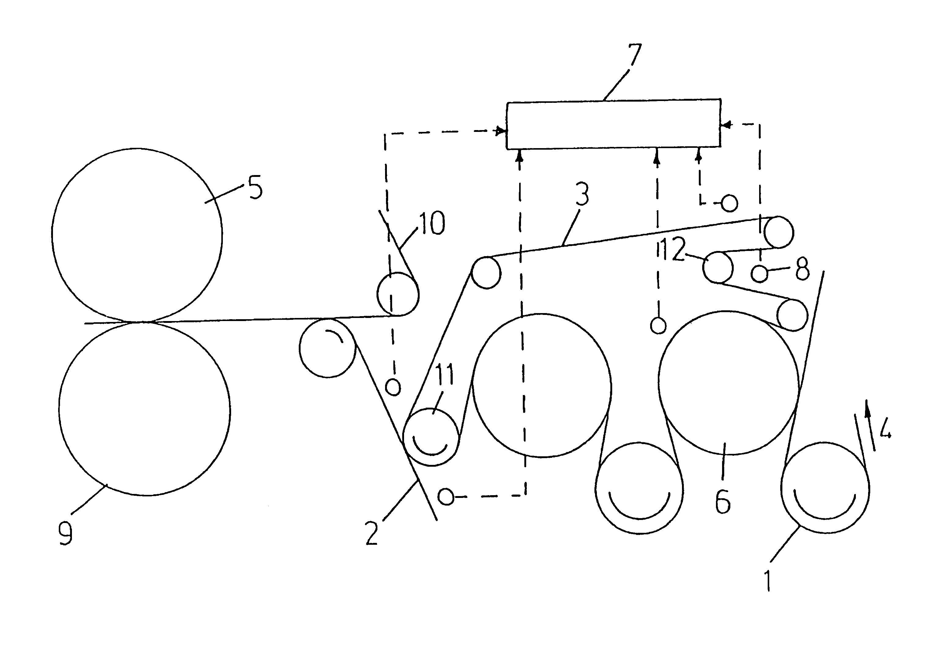
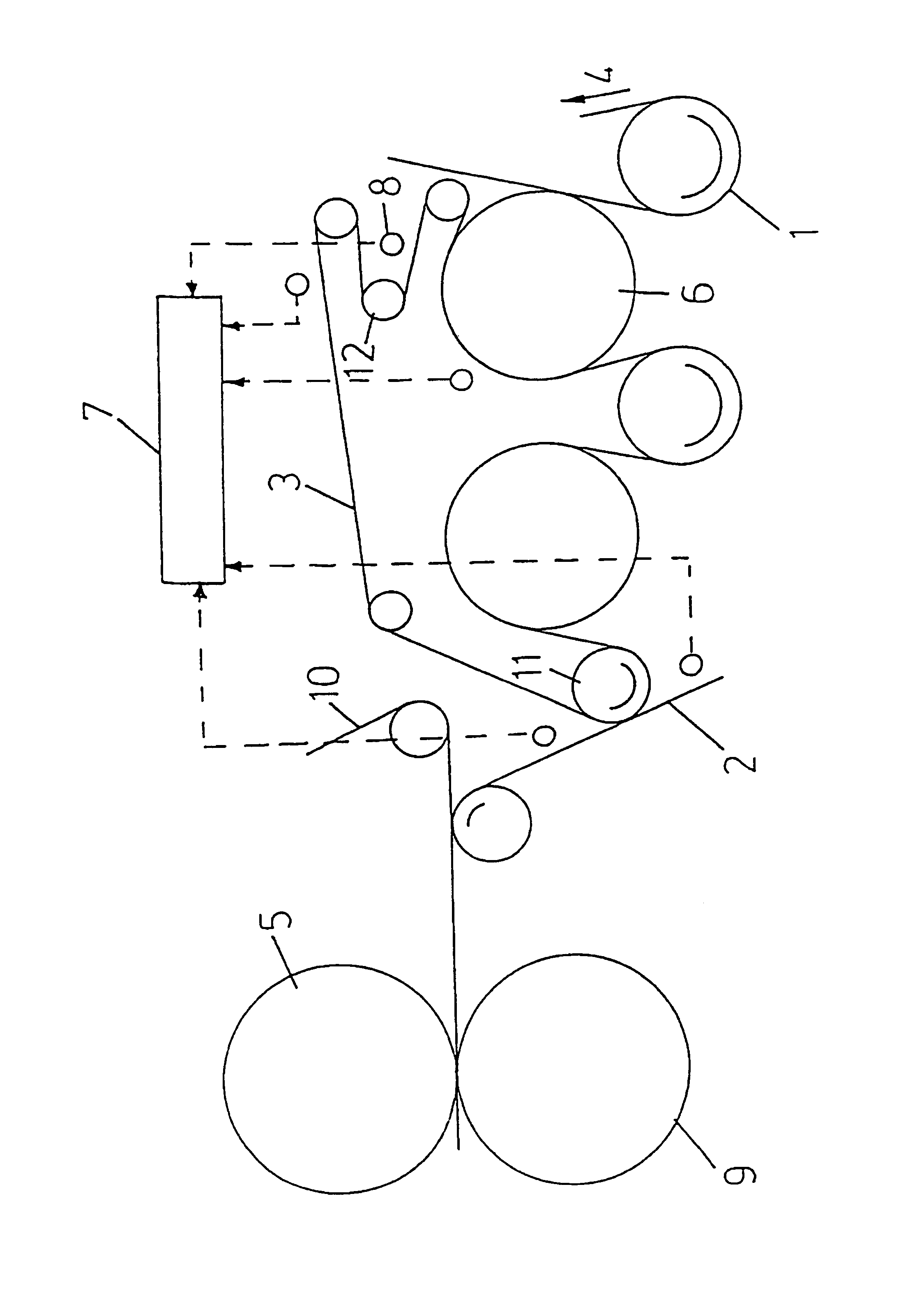
The press section is used to dewater the fibrous material web 1, whereby the fibrous material web 1 in this case runs through a press nip formed by two press rolls 5, 9 on both sides each with a belt 2, 10 in the form of a water-absorbing press felt.

For example, the upper press roll 5 is heated in this case to intensify the dew...


PUM


Abstract

A process and device to detect the presence of a fibrous material web in machines for manufacturing the same, whereby the fibrous material web is guided by at least one continuously circulating belt. The process includes measuring at least one of (1) a temperature of a side of the fibrous material web opposite the at least one belt while it is being supported by the at least one belt, (2) a temperature of a material web supporting side of the side of the at least one belt after transfer of the fibrous material web to a following unit, and (3) the temperature of a side of the at least one belt opposite the fibrous material web supporting side of the at least one belt. The process also includes detecting a change in the at least one measured temperature as an indicator of the presence or lack of fibrous material or the strip in an area in the machine in the vicinity of the measuring.

Description

The present application claims priority under 35 U.S.C. .sctn.119 of German Patent Application No. 101 31 281.4, filed on Jun. 28, 2001, the disclosure of which is expressly incorporated by reference herein in its entirety.1. Field of the InventionThe invention relates to a process to detect the presence of a paper, cardboard, tissue or other fibrous material web or a strip of the fibrous material web in machines for manufacturing and / or finishing the fibrous material web, whereby the fibrous material web is guided by at least one continuously circulating belt.2. Discussion of Background InformationIn order to be able to minimize the damage from a tear in the fibrous material web, it is important to detect the tear as early as possible. This makes it possible not just to reduce possible damage to the machine from a jam of the fibrous material web, but also to reduce the broke. In addition, it is also important for the control of the machine to detect the complete transfer of the fib...

Claims


Application Information

Patent Timeline
Patent Type & Authority Patents(United States)
IPC IPC(8): B65H20/06B65H20/00B65H26/00B65H26/02D21F7/04
CPCB65H20/06B65H26/025D21F7/04B65H2515/40B65H2801/84B65H2220/02
Inventor DICK, WOLFRAMMAYER, ROLANDPRUSSING, HOLGER
Owner VOITH PATENT GMBH
Why Eureka
Try Eureka