Electric apparatus with electric terminals and fused structures

a technology of electric terminals and fused structures, which is applied in the direction of basic electric elements, emergency protective devices, solid-state devices, etc., can solve the problems of limited capacity of the fuse holders between the terminals and load circuits of the prior-art array of fuse holders, impaired power rating, and difficulty in detecting the condition of a fuse blown, so as to improve the mounting of fuses and facilitate the detection of the condition

Inactive Publication Date: 2004-03-16
TELECT
View PDF7 Cites 16 Cited by
  • Summary
  • Abstract
  • Description
  • Claims
  • Application Information

AI Technical Summary

Benefits of technology

It is also an object of the invention to provide fuse holder arrays of increased capacity and power rating.
It is also an object of the invention to improve mounting of fuses so that their condition can more easily be discerned by maintenance and service personnel.

Problems solved by technology

In a similar vein, prior-art arrays of fuse holders between such terminals and load circuits had limited capacity with vulnerability to overheating and impaired power rating.
Moreover, prior-art fuse circuit designation cards used in conjunction with fuse holders were stored in envelopes that were vulnerable to burning.
Moreover, existing electric fuse arrangements often make it difficult for maintenance and service personnel in telephone exchanges and similar installations to become aware when a fuse has blown.
By way of example, existing arrangements mount fuses having spring-biased fuse condition flagging devices so that such flagging devices point away from the floor toward the ceiling when the fuse blows, and thereby are difficult to see by maintenance and service personnel.

Method used


Image

  • Electric apparatus with electric terminals and fused structures
  • Electric apparatus with electric terminals and fused structures
  • Electric apparatus with electric terminals and fused structures

Examples


Embodiment Construction

The drawings show electric apparatus and components according to preferred embodiments of the invention.

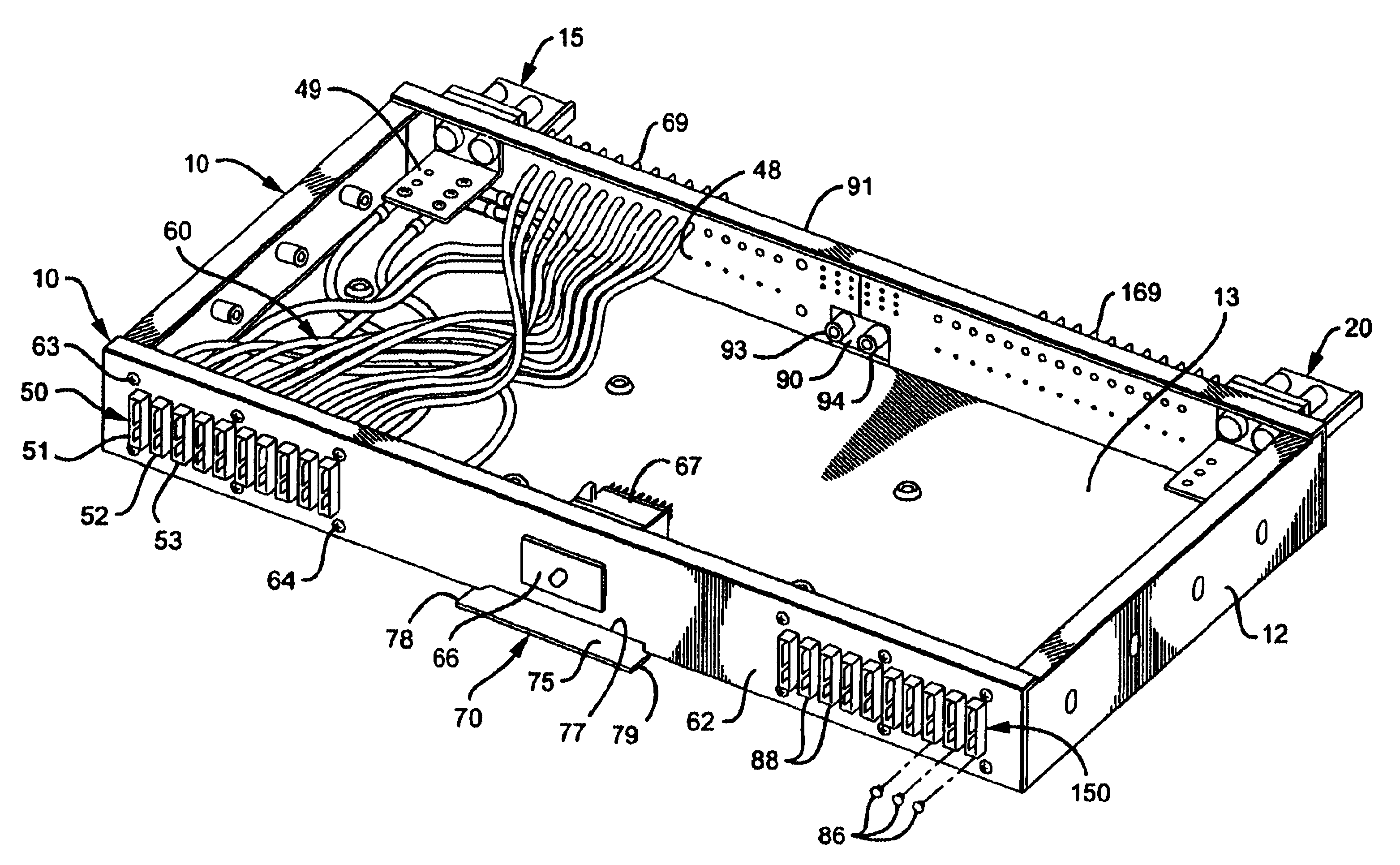
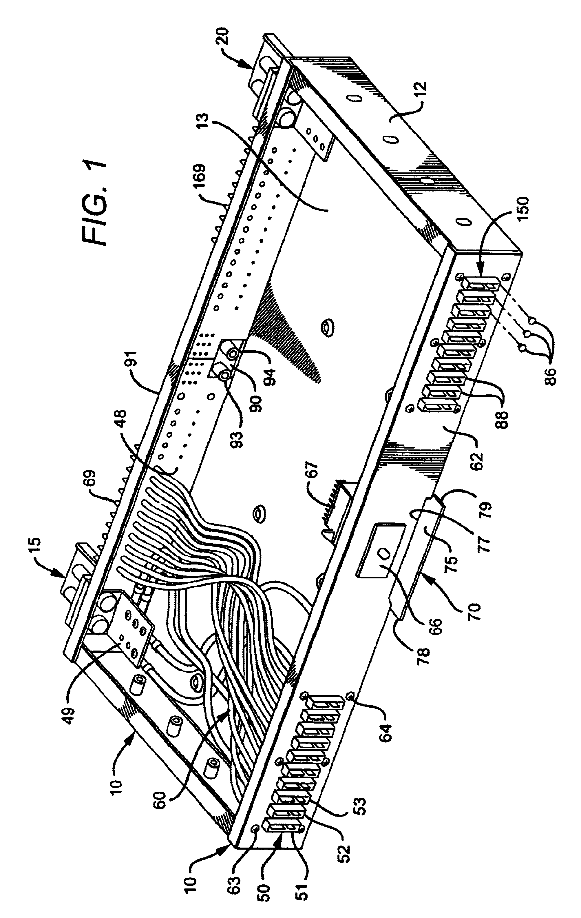
By way of example, FIG. 1 shows electric apparatus 10 in the form of a cabinet 12 including a panel 13 and several components 15, 20, 50, 60 and 70 that may be used in any combination or independently of each other. Similar apparatus have been used for years as power distribution units (PDUs), also known as fuse panels, in telephone exchange equipment, but the invention is not so limited.

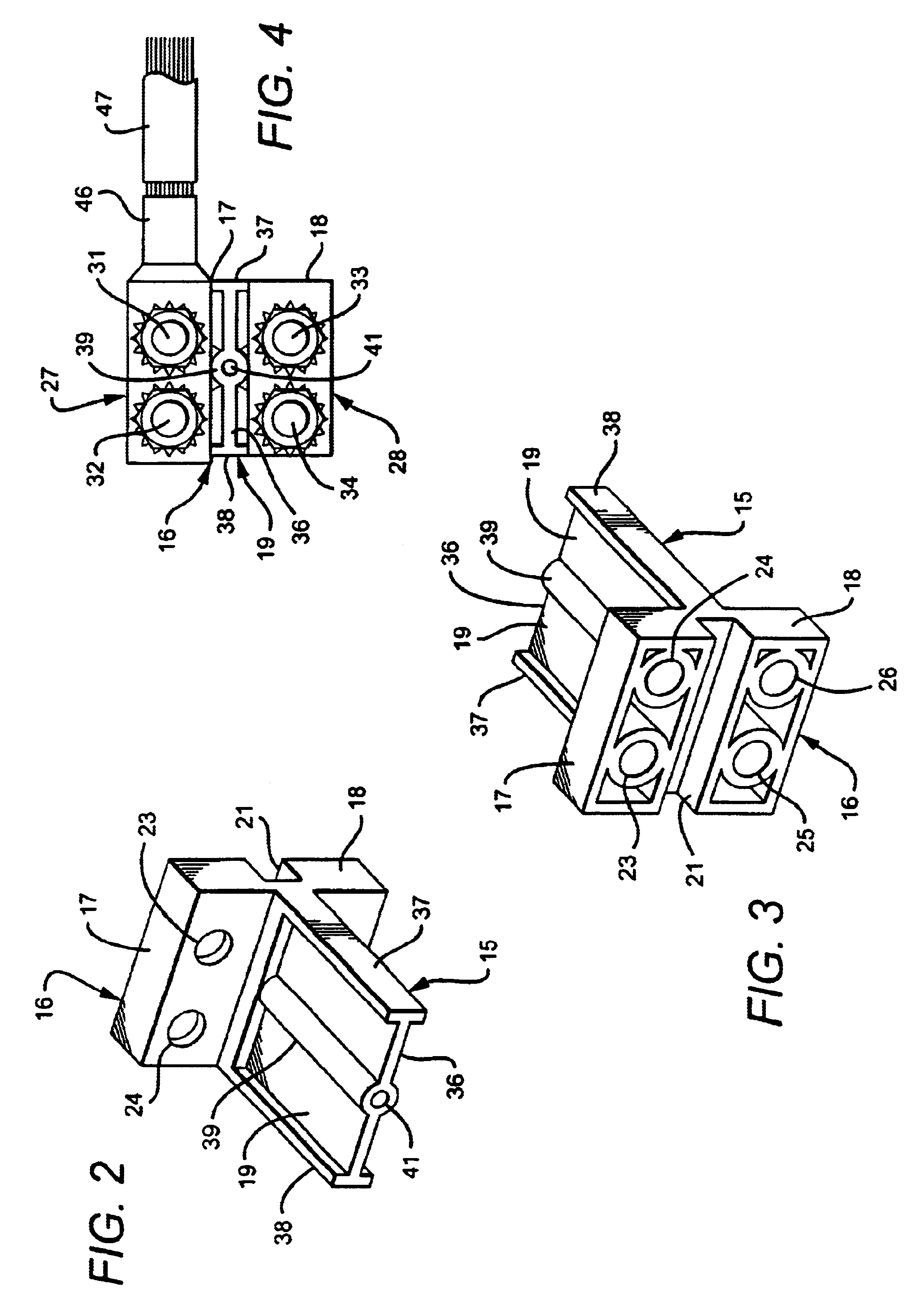
In this respect, FIGS. 1 to 7 show power terminal structures in the form of electric terminal devices with standoffs, including, for example, positive and negative terminals of a telephone or other direct-current system, or opposite terminals of an alternating current system, which may be used in the apparatus of FIG. 1 or in many other applications.

FIGS. 1 to 7 in particular show an integral input power terminal structure 15 of electrically insulating material according to an embodiment of the in...


PUM


Abstract

Electric apparatus having distinct electric terminals has an input power terminal of electrically insulating material, including a base of electric insulating material having a first electric terminal base portion and a second electric base portion spaced from that first electric base portion, and a barrier wall of insulating material on that base acting as an isolator between the first and second electric terminals on these base portions, and preferably also as a standoff for a protective cover. A plurality of electric fuse holders in that or other electric apparatus may be mounted in mutually spaced relationship, and a heat sink including a frame around that plurality of mutually spaced electric fuse holders is in heat-transfer relationship with these electric fuse holders, and includes a cross-piece between each adjacent pair of the mutually spaced electric fuse holders. A flame-resistant designation card for that or other apparatus has a first data-bearing section, a second data-bearing section, a first folding crease between such first and second data-bearing sections, a shorter third section adjacent that second data-bearing section, and a second folding crease between the shorter third section and the second data-bearing section. Fuse condition designation flags are rendered better visible by service personnel and fuse rating designation pins are better organized. Ground wire terminals are safeguarded against rotation and loosening.

Description

The subject invention relates to electric apparatus and to electric terminal structures and fused structures, such as used in telephone exchanges or otherwise.Despite a seeming abundance of electric terminal configurations, there has persisted a need for improved terminal structures possessing at least one or more of the following features:a stronger separation of opposite terminals,better accommodation of terminal elements and fasteners, cleaning facility between opposite terminals,standoff facility for terminal covers,strainless one-piece construction, andmanufacturability by molding or extrusion at a balanced cooling pattern.In a similar vein, prior-art arrays of fuse holders between such terminals and load circuits had limited capacity with vulnerability to overheating and impaired power rating.Moreover, prior-art fuse circuit designation cards used in conjunction with fuse holders were stored in envelopes that were vulnerable to burning.There also persisted a need for fused pan...

Claims


Application Information

Patent Timeline
Patent Type & Authority Patents(United States)
IPC IPC(8): H02G3/18H02G3/08
CPCH02G3/18H02G3/081
Inventor REYES, JEREMIAH G.SEVIER, RICHARD W.KEENAN, JAMES J.RAWLINS, JERRY C.ANDREASEN, PAUL E.BOWERS, RICHARD J.
Owner TELECT
Why Eureka
Try Eureka