Goods pallet

a pallet and good technology, applied in the field of pallets, can solve the problems of affecting the quality of pallets, and requiring regular repair

Inactive Publication Date: 2004-03-23
CATHERINE DUMOUCHEL +1
View PDF9 Cites 17 Cited by
  • Summary
  • Abstract
  • Description
  • Claims
  • Application Information

AI Technical Summary

Benefits of technology

An object of the invention is to propose a pallet of structure that is robust and simple.
A pallet made in this way is easily made by assembling together its various elements and it presents properties similar to those of conventional pallets, in particular wooden pallets, and possibly even better than those of pallets made of ordinary types of injected thermoplastic material. The channel section of the beam thus ensures good distribution of the weight supported by the pallet. In addition, this beam presents good mechanical strength because of its structure, thus making it possible, in particular compared with conventional wooden pallets, to avoid using a bottom cross-member uniting the brackets, which makes it possible to reduce the height of the pallet. In addition, by using such a beam, various portions of the conventional assembly are formed as a single piece (two cross-members and three blocks in the above-described prior art wooden pallet), thus reducing the number of parts and simplifying manufacture of the pallet. The cross beams can also be made out of materials which do not absorb moisture, thereby preventing moisture from rising into the goods supported by the pallet.
In a particular embodiment, the pallet comprises at least one stiffener element extending parallel to the support elements and at a distance therefrom between two opposite brackets, the stiffener element being formed by a plank-shaped beam, the bottom surface of the beam being grooved and the beam having at least one chamfer formed in at least one of its top longitudinal edges. The resulting pallet is thus particularly strong. This also makes it possible firstly to lighten the pallet and secondly to reduce the risk of impact between the stiffener element and the tips of forklift tines.
The cross beam then presents increased resistance to the impacts that the tines of forklift trucks can impart against the web of the cross beam.
This provides in simple manner a cross beam made of recycled material that is solid and bulky in structure. The part presents mechanical characteristics which are satisfactory, and in the preferred composition come close to those of wood, with this applying in particular to breaking strength, thereby enabling parts made of this material to be assembled in similar ways to wood.

Problems solved by technology

A drawback of such pallets is that they comprise a large number of elements (twenty-four for the most widespread pallet structure, namely: six support planks, three top cross-members, nine blocks, three bottom cross-members, and three base planks), which leads to assembly costs, labor costs, and stock management costs that are all relatively large.
The time required for manufacture is also relatively long.
Furthermore, wooden pallets are relatively fragile and need to be repaired regularly.
In addition, wooden pallets suffer from the drawback of taking up moisture, thereby increasing their weight.
Furthermore, when a pallet stands on a damp surface, moisture tends to rise as far as the support planks and possibly also to reach the goods stored on the pallet.

Method used


Image

  • Goods pallet
  • Goods pallet
  • Goods pallet

Examples


Embodiment Construction

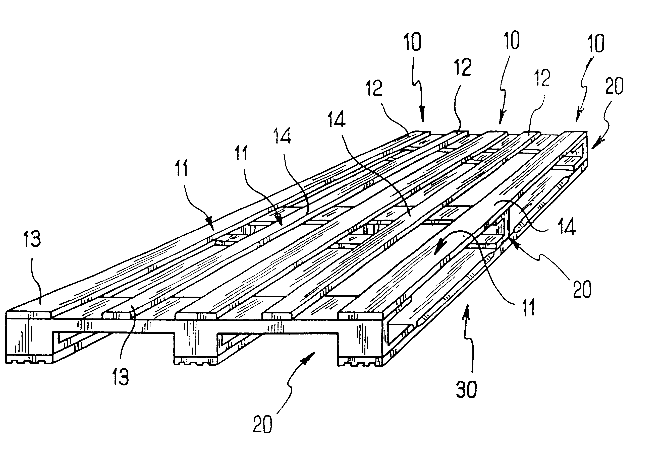
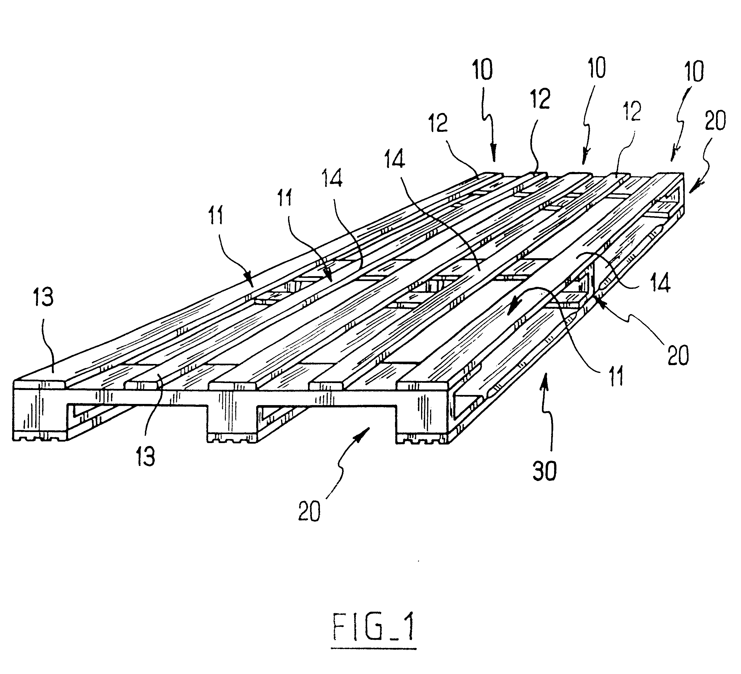
With reference to the figures, the pallet of the invention comprises support elements 10 in the form of planks having rough top surfaces 11. The support elements 10 are fixed via their opposite ends 12, 13 and their middle portions 14 to cross-connection beams 20.

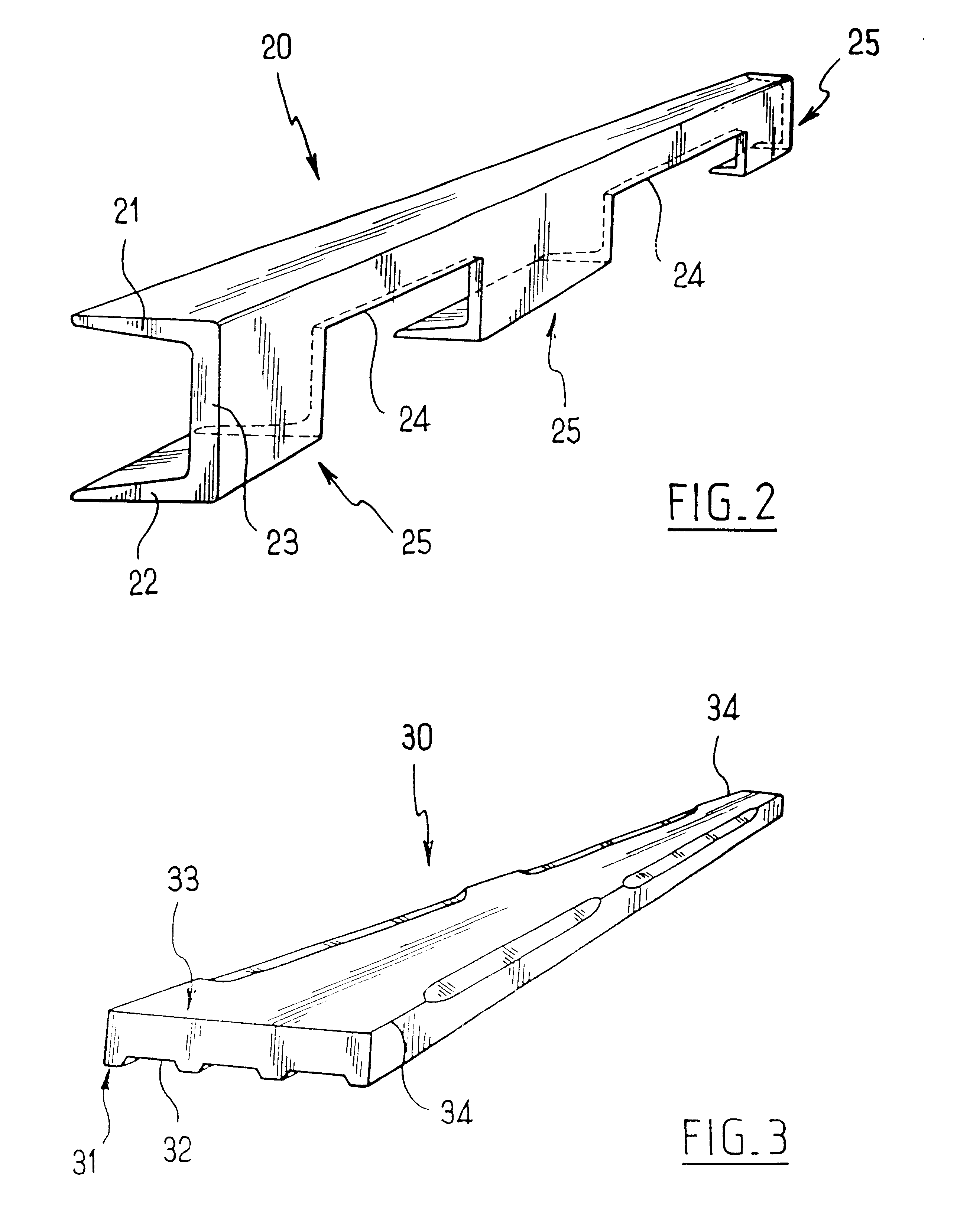
The cross-connection beams 20 are of channel section, each presenting a top flange 21 and a bottom flange 22 interconnected by a web 23. The support elements 10 are fixed to the top flange 21.

Two spaced-apart recesses 24 cut out both in the bottom flange 22 and in the web 23 serve to provide passages for the tines of a conventional type of forklift truck. Each cross-connection beam thus constitutes three brackets given overall references 25 and interconnected by the top flange 21. It should be observed at this point that each recess 24 is made in a bottom portion of the web 23 in such a manner that the remaining portion of the web 23 extends along the top of the recess between the brackets. Other recess configurations are p...


PUM


Abstract

A goods pallet comprising parallel supports having at least end portions fixed by structure to cross-connection elements, each cross-connection element comprising a beam of channel section having a top flange to which the support elements are fixed, and a web and a bottom flange which are both recessed by at least one notch to form two spaced-apart brackets on either side thereof that are integral with the top flange.

Description

In conventional manner, such a pallet is made of wood and generally comprises support planks on which goods are placed. The support planks are parallel to one another and they are held spaced apart from base planks which are likewise parallel to one another and to the support planks, by means of three cross spacer elements which are fixed to the base planks so as to interconnect them, with fixing being performed by nails passing through the support planks in the middle and at the ends. As a general rule, the spacer elements comprise three solid blocks, interconnected by top and bottom cross-members, and to which the support and base planks are fixed, respectively.A drawback of such pallets is that they comprise a large number of elements (twenty-four for the most widespread pallet structure, namely: six support planks, three top cross-members, nine blocks, three bottom cross-members, and three base planks), which leads to assembly costs, labor costs, and stock management costs that ...

Claims


Application Information

Patent Timeline
Patent Type & Authority Patents(United States)
IPC IPC(8): B65D19/00B65D19/32
CPCB65D19/0095B65D2519/00034B65D2519/00069B65D2519/00104B65D2519/00293B65D2519/00298B65D2519/00323B65D2519/00333B65D2519/00373B65D2519/00417B65D2519/00557B65D2519/00562B65D2519/00796B65D2519/00835
Inventor DUMOUCHEL, CATHERINE
Owner CATHERINE DUMOUCHEL
Why Eureka
Try Eureka