
Breathing apparatus and method for operation thereof for examining pulmonary mechanics of a respiratory system

a technology of pulmonary mechanics and breathing apparatus, which is applied in the direction of valve operating means/release devices, applications, diagnostic recording/measuring, etc., can solve the problems of difficult interpretation, high risk of respirator-induced lung damage (rils), and difficult time-consuming recording of curves

Inactive Publication Date: 2004-03-23
MAQUET CRITICAL CARE
View PDF9 Cites 89 Cited by
  • Summary
  • Abstract
  • Description
  • Claims
  • Application Information

AI Technical Summary

Benefits of technology

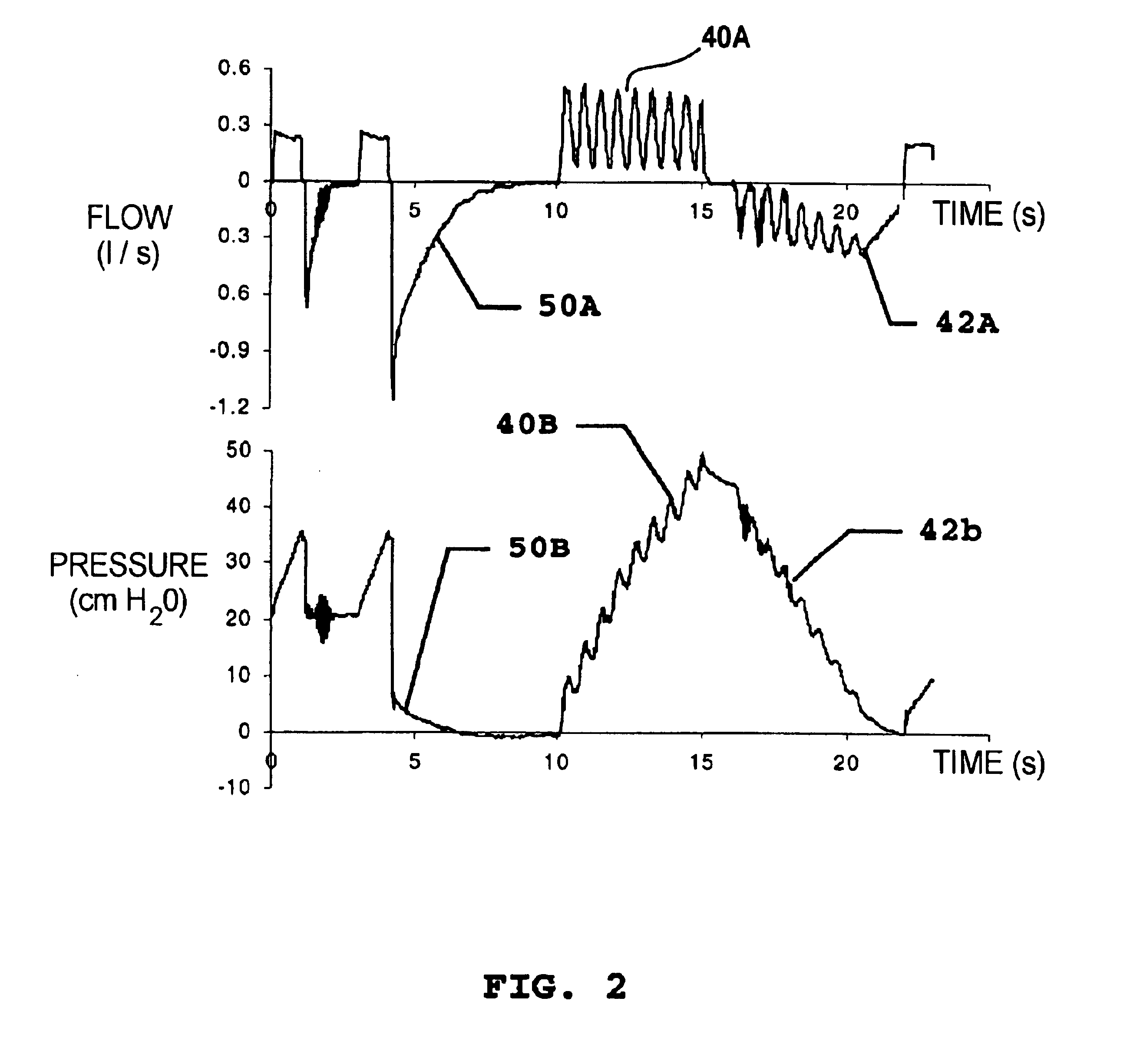
Modulation can be sinusoidal, triangular, quadratic or have some other regular shape. Declining or increasing modulation with a regular basic form or even completely irregular modulation can be used. Pressure can be measured inside the respiratory system, e.g. in the airways, or at some other location in the path of gas from the respiratory system. When pressure is not measured in the respiratory system itself, the corresponding pressure can be calculated from the measured pressure by compensating for the pressure drop in the system of tubing etc. Measuring the flow and integrating it determine the volume most easily. However, other ways of determining volume are possible.

Problems solved by technology

This has been questioned, however, since the morphology of the Pel.sub.l / V curve is influenced by complex phenomena and therefore difficult to interpret.
Multiple Pel.sub.l / V curves recorded at different levels of PEEP can supply more detailed information, but recording these curves is difficult and time-consuming.
This means that internal forces in the lung are particularly strong during recruitment, and this poses a great risk of respirator-induced lung damage (RILS).
Recording takes a long time.
This means that gas exchange in the form of gas uptake leads to artifacts, making accurate determination of hysteresis impossible.
This determination takes several minutes during which the patient's condition can change, thereby making accurate determination of hysteresis impossible in clinical settings.
No methods are available for accurate, automatic measurement of pressure-volume loops in clinical practice.

Method used


Image

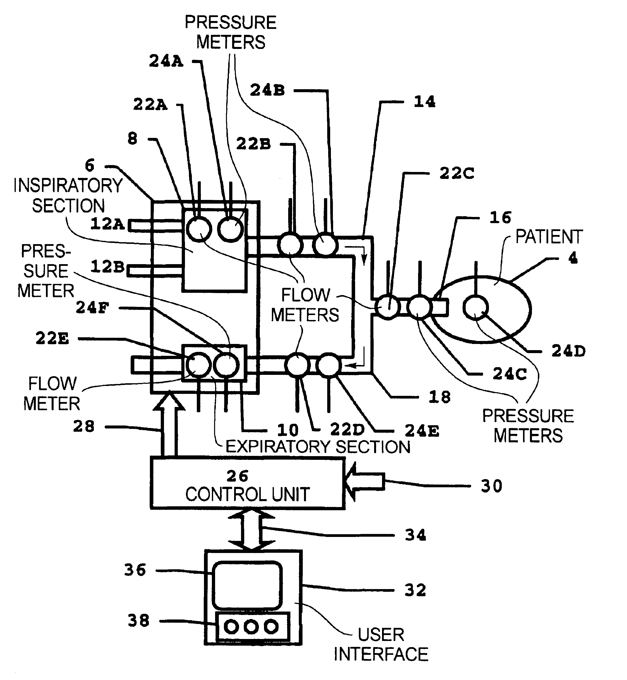
  • Breathing apparatus and method for operation thereof for examining pulmonary mechanics of a respiratory system
  • Breathing apparatus and method for operation thereof for examining pulmonary mechanics of a respiratory system
  • Breathing apparatus and method for operation thereof for examining pulmonary mechanics of a respiratory system

Examples


Embodiment Construction

No. of loops: =5

Starting values for pressure: =20, Step: -5 cmH20

No. of normal breaths between each loop: 6

Duration of preceding expiration: 6 s

End values for pressure, not selected, safety level: 50 cmH20

Volume range for loops: 1400 ml

Insufflation duration: 6 s

Exsufflation duration: 6 s

Sinusoidal modulation: 1.66 Hz Modulation depth: 100%

Time for measurement: At a manual command

Is the above correct, Yes / no? Yes

Answers entered by the operator during the dialogue in the above example are in italics.

The measurement sequence starts at a pre-selected time or after a manual command. According to the above dialog, the sequence has five loops, the first of which starts at a pressure of 20 cmH20, with subsequent loops at successively lower pressures.

The measurement sequence starts when the computer sends analog signals to the respirator for control of the respirator's rate and end-expiratory pressure (PEEP). The signals controlling frequency and PEEP have the levels required for subsequent ...


PUM


Abstract

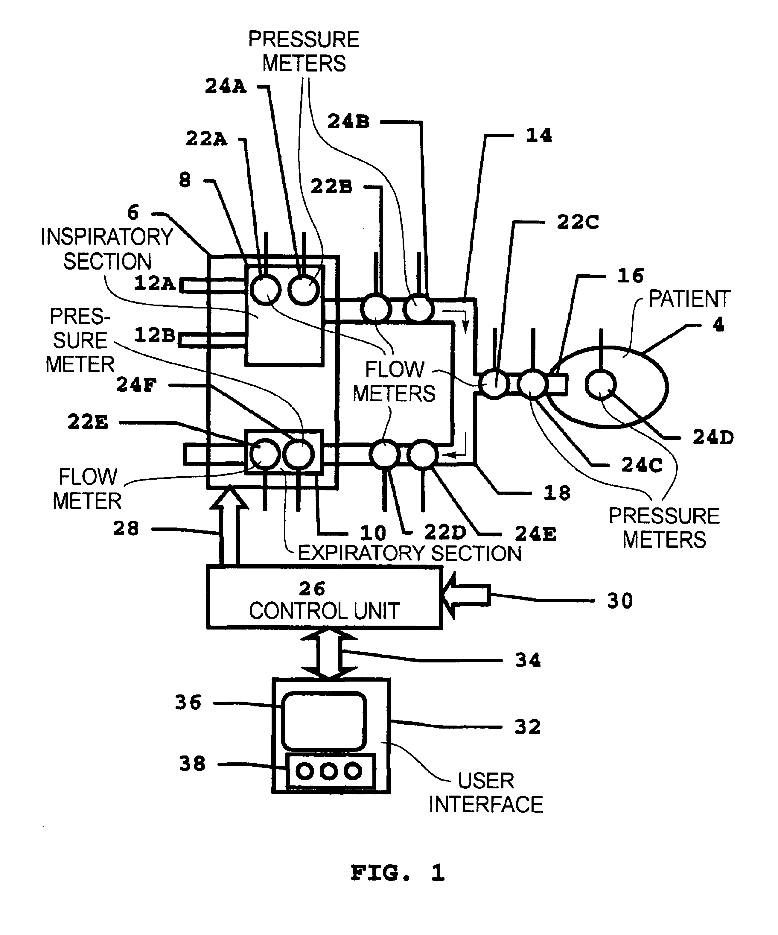
In an apparatus and method for examining the pulmonary mechanics of a respiratory system, in order to obtain information about the mechanical properties of the respiratory system's lungs, during an expiration of a flow of gas streaming out of the respiratory system is modulated, the volume of gas streaming out of the respiratory system is determined, the variation in pressure in the respiratory system is determined, and an expiratory pressure-volume relationship is determined from the expiratory volume and the expiratory variation in pressure.

Description

1. Field of the InventionThe present invention relates to a method for examining the pulmonary mechanics of a respiratory system.The present invention also relates to a breathing apparatus system operating according to the method.2. Description of the Prior ArtA ventilator is an apparatus for ventilating or supporting spontaneous ventilation of the lungs of a human being or an animal, hereafter referred to as the `patient`. The procedure generally employed for tailoring a ventilator's operation to physiological conditions prevailing in the patient is for the responsible care-provider to obtain as much information as possible about the patient, information about the respiratory organs in particular. This type of information often can be obtained when the ventilator is equipped with sensors for airway pressure, flow or volume delivered to or removed from the respiratory organs. Measurement systems, however, often are formed of one or a number of devices independent of the ventilator. ...

Claims


Application Information

Patent Timeline
Patent Type & Authority Patents(United States)
IPC IPC(8): A61B5/08A61B5/085A61M16/00
CPCA61B5/085A61M16/00A61M16/0006A61M2016/0021A61M2016/0036A61M2016/0039A61M2016/0042A61M16/0051A61M16/026
Inventor JONSON, BJORN
Owner MAQUET CRITICAL CARE
Learn More