Two-wheeled vehicle with rear suspension

a rear suspension and two-wheel technology, applied in the field of two-wheeled vehicles, can solve the problems of unsatisfactory frame displacement, particularly complex embodiment described in document u.s. patent no. 5, 637, etc., and achieve the effect of improving overall rigidity, low manufacturing cost, and accurate positioning of circular eccentrics and bottom brackets

Inactive Publication Date: 2004-03-30
DECATHLON SA
View PDF15 Cites 41 Cited by
  • Summary
  • Abstract
  • Description
  • Claims
  • Application Information

AI Technical Summary

Benefits of technology

Thus, the rigidity of the rear suspension is provided by the circular eccentric and it is the plate forming the connection rod that allows said suspension to move.
The portion of the front frame which is designed to receive the bottom bracket and the circular eccentric is preferably a junction piece made as a single machined part, the unfinished part being obtained by forging, molding, or extrusion. This method of implementation presents several advantages: low manufacturing cost, accurate positioning of the circular eccentric and of the bottom bracket, better overall rigidity. When the front frame is of traditional structure, the junction piece is assembled with the seat tube and with the diagonal tube.
In a preferred variant embodiment, the damping system, the oscillating rear assembly, and the plate forming a connecting rod are secured to one another about a common pivot pin. This thus provides a common fixing for the connecting rod and for the damping system with the oscillating rear assembly, thereby reducing the number of pivots that need to be made and also the number of assemblies, and thus also achieving a significant saving of weight.
In a preferred embodiment, the damping system acts substantially in line with a rectilinear portion of the oscillating rear assembly having a first end fixed to said damping system and a second end carrying the rear wheel. This particular disposition provides optimum transmission of forces from the rear wheel on the damping system.

Problems solved by technology

This interaction between the suspension and the transmission can give rise to a so-called "pumping" effect which leads to undesirable displacement of the frame which moves down and up under the effect of energetic pedaling.
It is also to be observed that the embodiment described in document U.S. Pat. No. 5,259,637 is particularly complex, implementing a very large number of parts connecting the two links indirectly to the damping system which is formed by a compression spring.

Method used


Image

  • Two-wheeled vehicle with rear suspension
  • Two-wheeled vehicle with rear suspension
  • Two-wheeled vehicle with rear suspension

Examples


Embodiment Construction

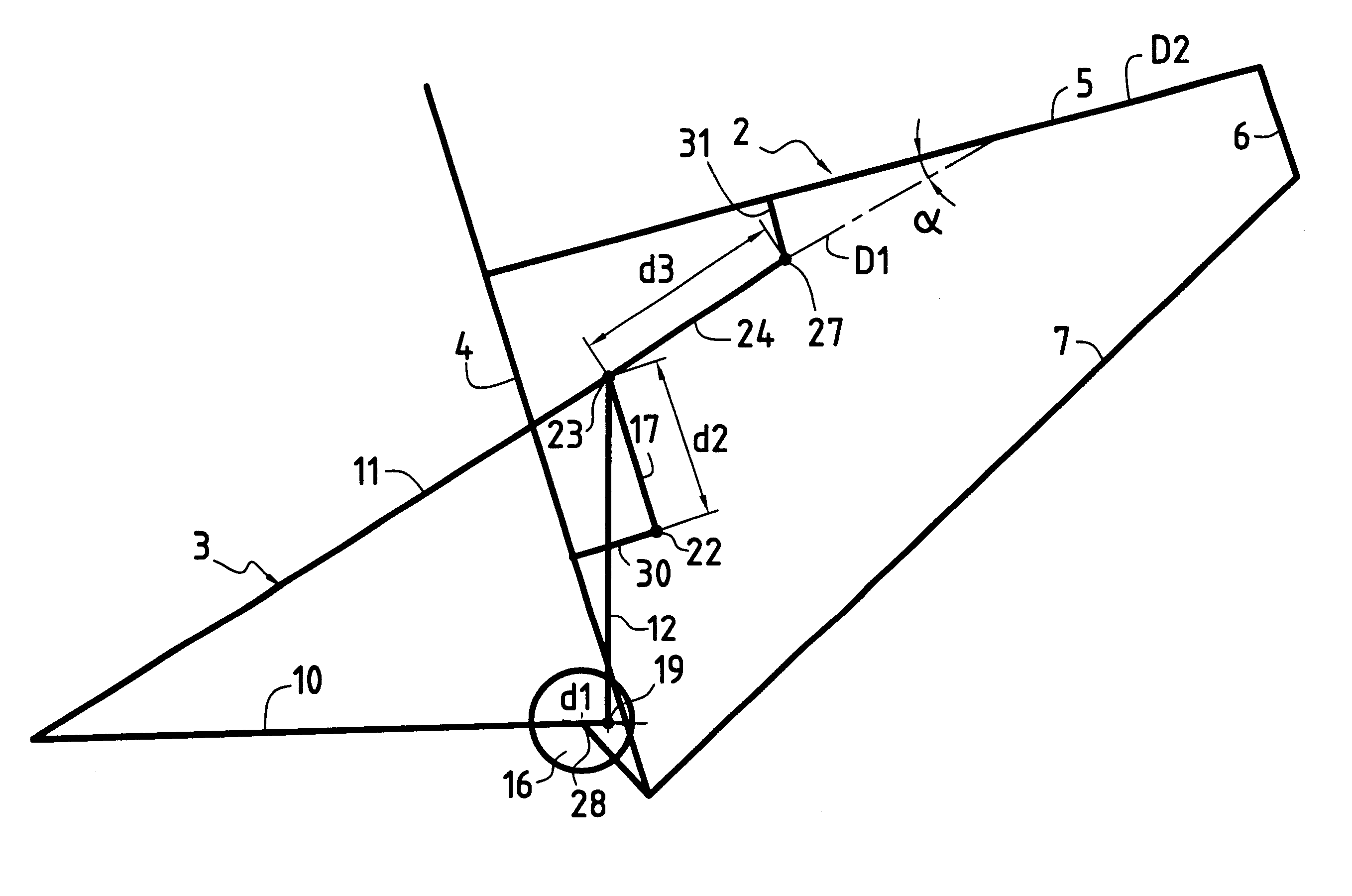
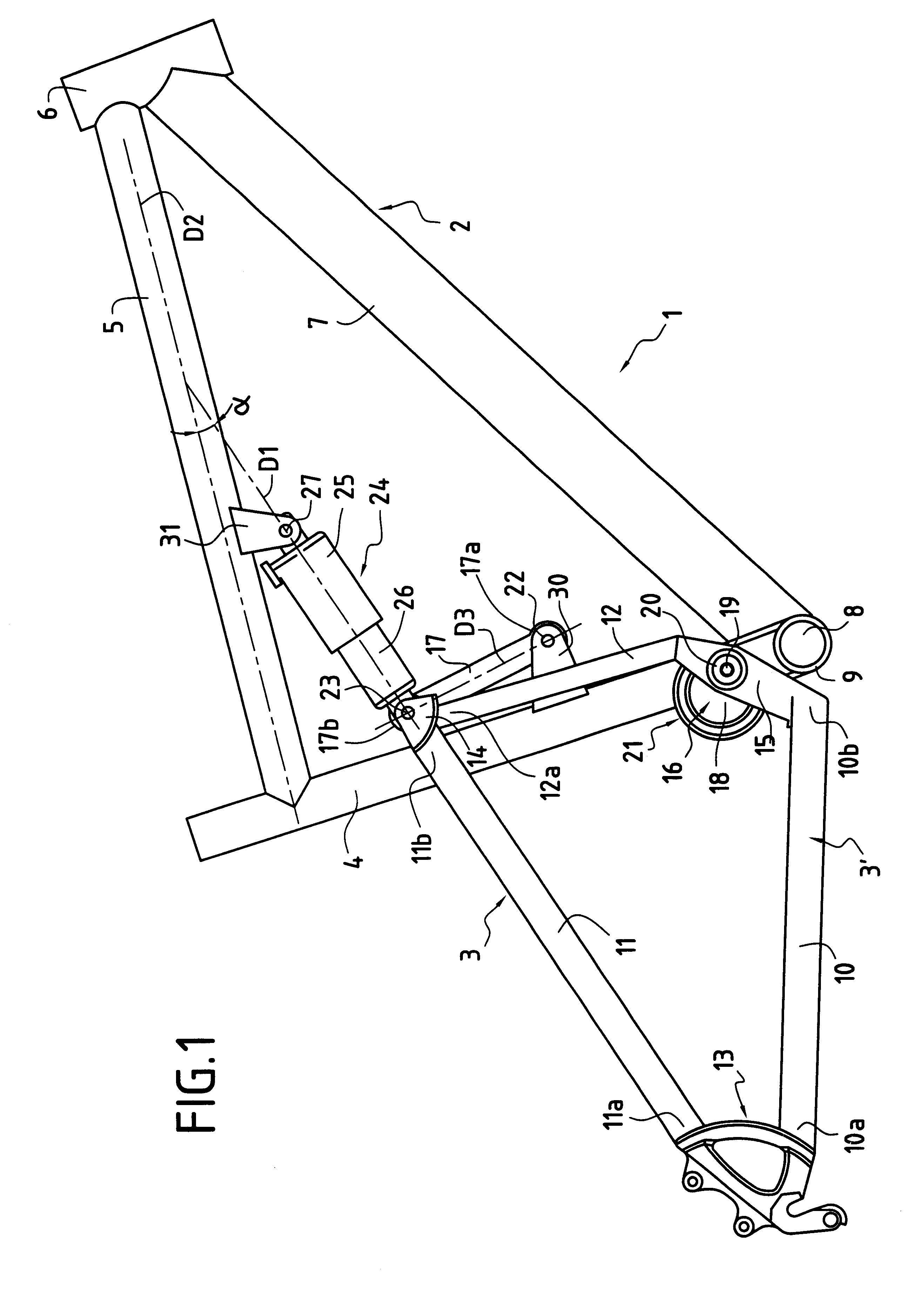
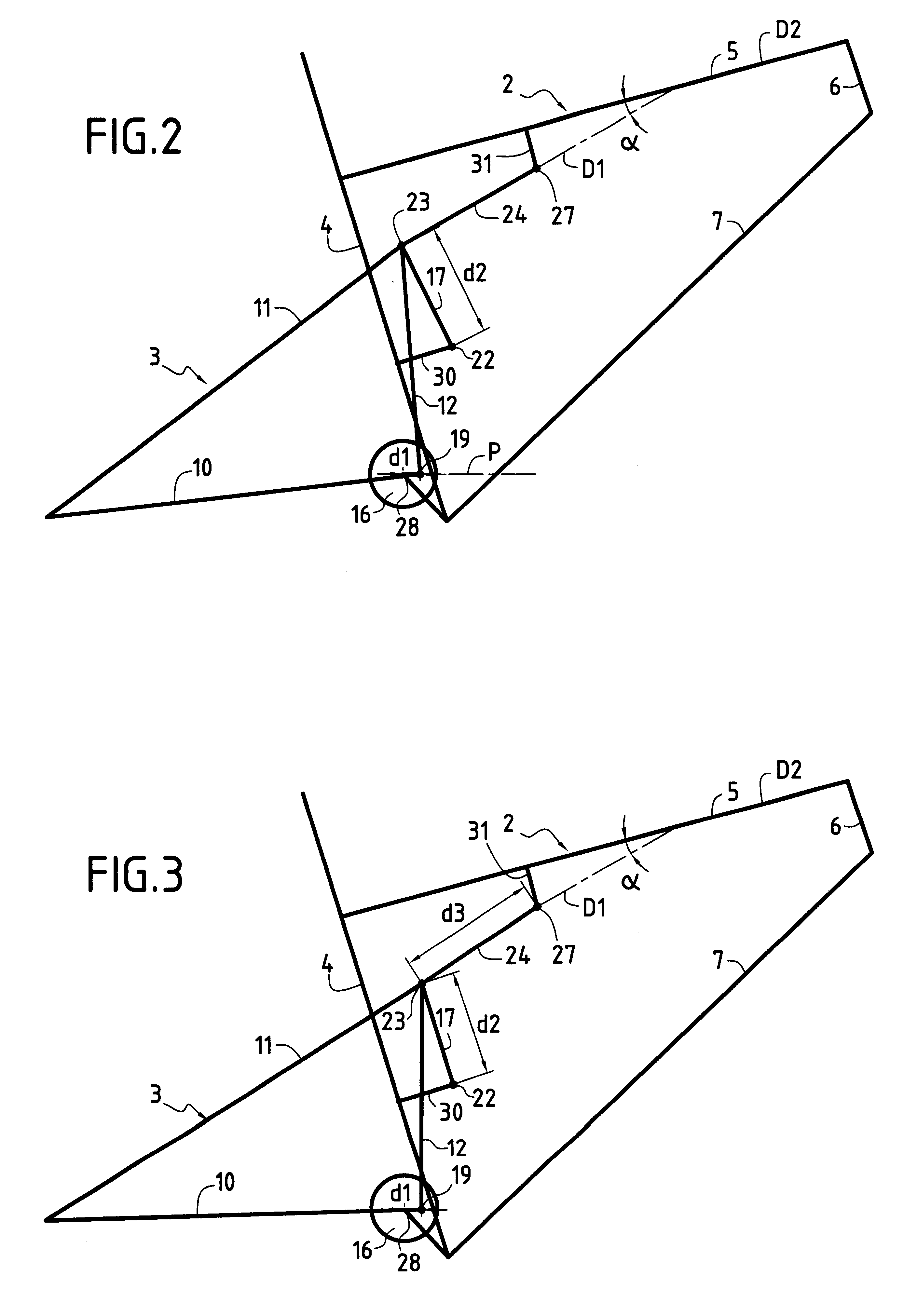
The mountain bike 1 with rear suspension which is shown in part in FIG. 1 comprises a front frame 2 of relatively conventional structure and an oscillating rear assembly 3.

The front frame 2 comprises four tubes, respectively the seat tube 4, the top cross-bar 5, the head tube 6, and the diagonal tube 7. The bottom bracket 8 is mounted in a housing 9 formed at the bottom end of the seat tube where the seat tube 4 intersects the diagonal tube 7.

The oscillating rear assembly 3 carries the driving rear wheel (not shown). It is constituted by two subassemblies 3', one of which is visible in FIG. 1, the subassemblies being disposed on either side of the midplane of the front chassis 2 and being connected to each other in particular via two pivot connections as described below.

Each subassembly 3' is generally triangular in configuration, having-a chain-stay tube 10, a seat stay tube 11, and a reinforcing tube 12. The rear portions 10a and 11a respectively of the chain-stay tube 10 and of t...


PUM


Abstract

A two-wheeled vehicle, in particular a bicycle or a mountain bike, the vehicle being fitted with a rear suspension and comprising a front frame carrying a bottom bracket and an oscillating rear assembly carrying a driving rear wheel, said frame and said rear assembly being connected to each other via two pivot connections and via a damping system, wherein the first pivot connection is formed by a circular eccentric constituted in a casing carrying an eccentric pin, said casing being mounted to pivot in a housing in the front frame, while the rear assembly is fixed to the eccentric pin on either side of the casing, and wherein the second pivot connection is formed by a connecting rod constituted by a simple plate disposed in the general direction of the frame.

Description

The present invention relates to a vehicle of the two-wheeled type, in particular a bicycle or more particularly a mountain bike, fitted with rear suspension.A mountain bike may conventionally comprise two suspensions, a front suspension and a rear suspension. The front suspension generally consists in a telescopic fork. The rear suspension comprises an oscillating assembly and a damping system. The oscillating assembly which supports the rear wheel is connected to the front frame of the bike via one or more pivot connections. The function of the damping system is to suspend the user-supporting frame of the bike elastically while damping shocks due to vertical deflection of the rear wheel. A function of the pivot connection(s) is to guide the vertical movement of said rear wheel that result from irregularities in the terrain.In a first type of rear suspension, the bottom bracket forms an integral portion of the oscillating assembly so that the suspension has no direct influence on t...

Claims


Application Information

Patent Timeline
Patent Type & Authority Patents(United States)
IPC IPC(8): B62K25/28B62K25/04
CPCB62K25/286
Inventor ASSIER, DENIS
Owner DECATHLON SA
Why Eureka
Try Eureka